2 power supply transitions, Figure 25. vhpfilt transitions, 3 adapt to output mode (setting 11) – Cirrus Logic CS42L56 User Manual
Page 42: Figure 25.vhpfilt transitions, Cs42l56
42
DS851F2
CS42L56
4.5.1.3
Adapt to Output Mode (setting 11)
When the Adaptive Power bits are set to 11, the CS42L56 decides which of the two sets of rail voltages
to send to the amplifiers based solely upon the level of the signal being sent to the amplifiers. If the signal
that is sent to the amplifiers would cause the amplifiers to clip when operating on the lower set of rail volt-
ages, the control logic instructs the charge pump to provide the higher set of rail voltages (±VCP) to the
amplifiers. If the signal that is sent to the amplifiers would not cause the amplifiers to clip when operating
on the lower set of rail voltages, the control logic instructs the charge pump to provide the lower set of rail
voltages (±VCP/2) to the amplifiers. This mode of operation eliminates the need to advise the CS42L56
of volume settings external to the device.
Note:
Signal detection is implemented using digital circuitry. This mode should, therefore, not be used
with analog passthrough (PGA to HP/Line).
4.5.2
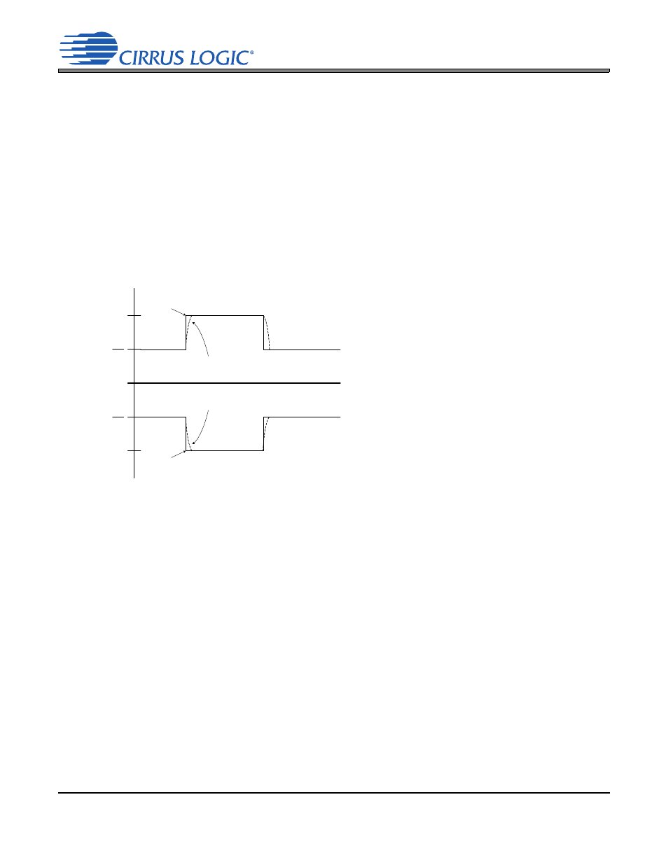
Power Supply Transitions
Charge pump transitions from the lower set of rail
voltages to the higher set of rail voltages occur on
the next FLYN/P clock cycle. Despite the fast re-
sponse time of the system, the capacitive ele-
ments on the VHPFILT pins prevent the rail
voltages from changing instantaneously. Instead,
the rail voltages ramp up from ±VCP/2 to ±VCP
based on the time constant created by the output
impedance of the charge pump and the capacitor
on the VHPFILT pin (the transition time is approx-
imately 20 µs).
This behavior is detailed in
. During this
charging transition, a high dv/dt transient on the in-
puts may briefly clip the outputs before the rail
voltages charge to the full ±VCP level. This transi-
tory clipping has been found to be inaudible in lis-
tening tests.
When the charge pump transitions from the higher set of rail voltages to the lower set, there is a one sec-
ond delay before the charge pump supplies the lower rail voltages to the amplifiers. This hysteresis en-
sures that the charge pump does not toggle between the two rail voltages as signals approach the clip
threshold. It also prevents clipping in the instance of repetitive high level transients in the input signal. The
diagram for this transitional behavior is detailed in
.
+VCP
-VCP
-VCP
2
+VCP
2
Ideal Transition
Ideal Transition
Actual Transition caused
by VHPFILT Capacitor
Actual Transition caused
by VHPFILT Capacitor
Time
Figure 25. VHPFILT Transitions