1 power control options, Figure 21. class h volume-adapt paths, Figure 21.class h volume-adapt paths – Cirrus Logic CS42L56 User Manual
Page 39: Cs42l56, 2 adapt to volume mode (setting 00), Referenced control register location
DS851F2
39
CS42L56
4.5.1
Power Control Options
The method by which the CS42L56 decides which set of rail voltages is supplied to the amplifier output
stages depends on the settings of the Adaptive Power bits (ADPTPWR) found in
dress 08h)” section on page 63
. As detailed in this section, there are four possible settings for these bits:
standard Class AB mode (settings 01 and 10), adapt to volume mode (setting 00) and adapt to signal (set-
ting 11).
4.5.1.1
Standard Class AB Mode (setting 01 and 10)
When the Adaptive Power bits are set to either 01 or 10, the rail voltages supplied to the amplifiers will be
held to ±VCP/2 or ±VCP, respectively. For these two settings, the rail voltages supplied to the output stag-
es are held constant, regardless of the signal level, internal volume settings, or the settings of the AIN and
DIN advisory volume registers. In either of these two settings, the amplifiers in the CS42L56 simply oper-
ate in a traditional Class AB configuration.
4.5.1.2
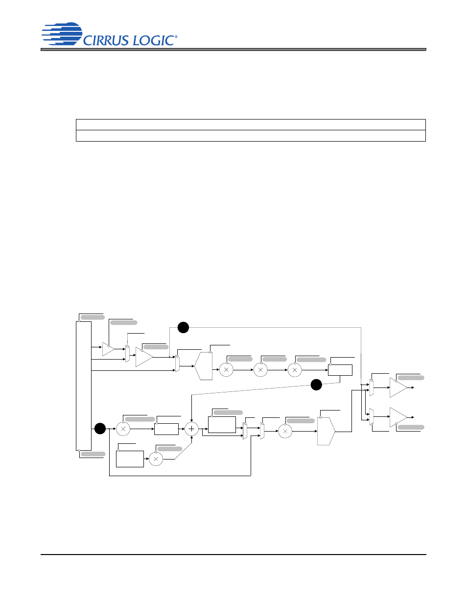
Adapt to Volume Mode (setting 00)
When the Adaptive Power bits are set to 00, the Class H controller decides which set of rail voltages to
send to the amplifiers based upon the gain and attenuation levels of all active internal processing blocks.
The active processing blocks are determined by the signal path configured; the configured path then dic-
tates which volume settings affect the controller. The paths available in the CS42L56 are (1) analog-in to
analog-out, (2) analog-in/digital-mix to analog-out and (3) digital-in to analog out.
Certain controls for the processing blocks in the signal path (such as B=A, mux, swap, mix and various
enables) do not directly affect the controller’s total volume sum. These controls do, however, have an in-
direct effect since they determine how the volume setting of the relevant processing block contributes to
the controller’s sum. These controls (italicized in
) determine whether or not the associated vol-
Referenced Control
Register Location
ADPTPWR[1:0]...................
“Adaptive Power Adjustment” on page 63
PGAAVOL [5:0]
PGAB=A
PDN_ADCx
ADCB=A
DIGSUM[1:0]
ADCxMUX[1:0]
Beep
Generator
AMIXxMUTE
AMIXxVOL [6:0]
BPVOL [4:0]
BASS[3:0]
TREB[3:0]
PLYBCKB=A
PDN_DSP
0 to -96dB
+12 to -51.5dB
ADCxMUTE
ADCxATT[7:0]
Mix/
Swap
ADCxSWAP[1:0]
PMIXxMUTE
PMIXxVOL[6:0]
+12 to -51.5dB
Mix/
Swap
PMIXxSWAP[1:0]
+6 to -50dB
TCEN
Bass/Treble
Boost/Cut
MSTxMUTE
MSTxVOL[7:0]
+12 to -102 dB
In
put
A
dv
is
or
y
Vo
lu
m
e
Di
g
ita
l
A
na
lo
g
0 to -102dB
AINADV[7:0]
0 to -102dB
DINADV[7:0]
HPxVOL [6:0]
HPxMUTE
PDN_HPx[1:0]
HPDETECT (pin)
LINExVOL [6:0]
LINExMUTE
PDN_LINx[1:0]
HPDETECT (pin)
HPxMUX
LINExMUX
+12 to -6dB
+12 to -60dB
+12 to -60dB
DAC
1
2
3
BEEP[1:0]
+12 to -10.5dB
PGA
LINE
HP
Non-volume controls (italicized ) affect how the Class H
controller interprets the various volume settings.
0 or +20dB
BOOSTx
PDNMICx
+10 or +20dB
ADC
MICxBOOST
Figure 21. Class H Volume-Adapt Paths