3 microphone inputs, Figure 17. mic input mix w/common mode rejection, 4 optional vcm buffer – Cirrus Logic CS42L56 User Manual
Page 34: 5 automatic level control (alc), 1 external passive components, Figure 17.mic input mix w/common mode rejection, Cs42l56
34
DS851F2
CS42L56
4.2.3
Microphone Inputs
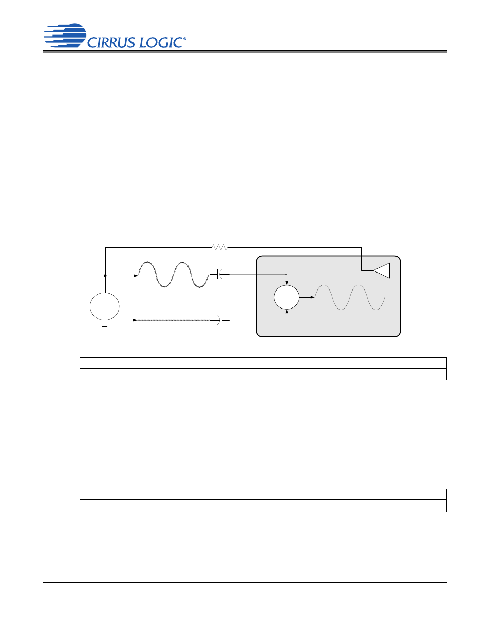
Any of the line inputs can be configured as a microphone input by using the MICBIAS pin to power the
external microphone circuit and by configuring the additional +10 or +20 dB gain in the PGA to properly
boost the low-level microphone signal.
4.2.3.1 External Passive Components
The analog inputs are internally biased to VQ. Input signals must be AC coupled using external capacitors
with values consistent with the desired high-pass filter design. The analog input resistance may be com-
bined with an external capacitor to achieve the desired cutoff frequency. The equation below gives an ex-
ample:
An electrolytic capacitor must be placed such that the positive terminal is positioned relative to the side
with the greater bias voltage. The MICBIAS voltage level is controlled by the BIAS_LVL[1:0] bits.
The MICBIAS series resistor must be selected based on the requirements of the particular microphone
used.
4.2.4
Optional VCM Buffer
Leaving an analog input pin floating when not being used might inject distortion in the analog input signal
path. To prevent this, the analog inputs may be internally biased to VCM by using a weak internal VCM
buffer when not being used. The VCM buffer outputs a weakly buffered version of the internal common-
mode voltage and biases the chip-side of the analog input AC-coupling capacitor to a constant DC level.
This prevents the analog signal from being distorted when that particular channel is not selected by either
the PGA or ADC input MUX. If an analog signal is routed to any place other than just the CS42L56, it is
recommended to set this bit to 0b. If all analog signals are only routed to the CS42L56, this bit may be left
set to 1b.
4.2.5
Automatic Level Control (ALC)
The function of the ALC is to maintain the level of the analog input signal between the maximum and min-
imum threshold settings programmed in the ALCMAX[2:0] and ALCMIN[2:0] registers. When enabled, the
ALC monitors the signal level after the digital volume control block in the input signal path and detects
Referenced Control
Register Location
BIAS_LVL[1:0] .....................
“Microphone Bias Output Level” on page 77
Referenced Control
Register Location
PDN_VBUF[1:0]...................
“Power Down VCM Bias Buffer” on page 58
fc
1
2
4 k
1 F
--------------------------------------------
39.79 Hz
=
=
MICx+
MICx-
+
+
MICBIAS
//
//
Figure 17. MIC Input Mix w/Common Mode Rejection