Figure 24. hp/line channel effects, Figure 24.hp/line channel effects, Cs42l56 – Cirrus Logic CS42L56 User Manual
Page 41
DS851F2
41
CS42L56
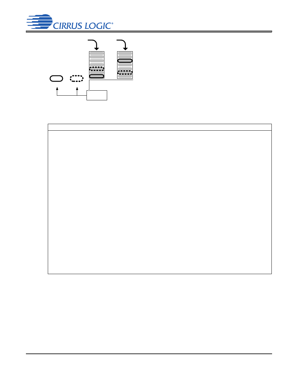
Effect of Volume Sum in HP or Line Paths
Since the HP and the Line amplifiers also share the same sup-
ply, the explanation above applies to the total gain/attenuation
set in the HP and Line amplifiers. If enabled, the volume set-
tings in the path of both amplifiers are considered before the
charge pump supplies the appropriate rail voltage.
Referenced Control
Register Location
AINADV[7:0] ........................
MICxBOOST .......................
PDNMICx ............................
PGAxVOL............................
ADCxMUX ...........................
ADCxMUTE.........................
DIGSUM[1:0] .......................
PDN_DSP ...........................
HPxVOL[7:0] .......................
LINExVOL[7:0] ....................
MSTxVOL[7:0].....................
MSTxMUTE.........................
AMIXxVOL[6:0]....................
PMIXxVOL[6:0]....................
DINADV[7:0]........................
ADCxSWP...........................
PCMxSWP ..........................
HPxMUX..............................
LINExMUX...........................
HPxMUTE ...........................
LINExMUTE ........................
PDN_HPx ............................
PDN_LINEx .........................
TREB...................................
BASS...................................
TCEN...................................
BEEP...................................
BPVOL ................................
ADCB=A ..............................
PGAB=A ..............................
BOOSTx ..............................
PLYBCKB=A........................
“Analog Input Advisory Volume” on page 69
“PGA x Preamplifier Gain” on page 77
“Power Down MIC Bias” on page 59
“PGAx Volume” on page 78
“ADC x Input Select” on page 75
“ADC Mute” on page 76
“Digital Sum” on page 76
“Power Down DSP” on page 66
“Headphone Volume Control” on page 84
“Line Volume Control” on page 84
“Master Volume Control” on page 70
“Master Playback Mute” on page 67
“ADC Mixer Channel x Volume” on page 67
“PCM Mixer Channel x Volume” on page 68
“Digital Input Advisory Volume” on page 69
“ADC Mix Channel Swap” on page 74
“PCM Mix Channel Swap” on page 74
“Headphone Input Select” on page 83
“Line Input Select” on page 83
“Headphone Channel x Mute” on page 83
“Line Channel x Mute” on page 84
“Headphone Power Control” on page 59
“Line Power Control” on page 60
“Treble Gain” on page 73
“Bass Gain” on page 73
“Tone Control Enable” on page 73
“Beep Configuration” on page 72
“Beep Volume” on page 72
“ADC Channel B=A” on page 76
“PGA Channel B=A” on page 76
“Boostx” on page 77
“Playback Channels B=A” on page 66
-10.5 dB
case1
case2
Class H
Controller
HP/LINE Supply
Decision:
-10.5 dB
case2
case1
of Line
Path
=
=
VCP
VCP/2
of HP
Path
Case 1 Result
Case 2 Result
Figure 24. HP/Line Channel Effects