Figure 22. volume sum effects, Figure 23. channel/amp effect, Cs42l56 – Cirrus Logic CS42L56 User Manual
Page 40
40
DS851F2
CS42L56
ume setting should be factored in with the volume settings of other control blocks in the signal path.
The Class H controller can be affected by the combined effect of all the volume settings in the relevant
path or the maximum sum in each channel (A, B) and the maximum sum in each amplifier (HP, Line). To
determine the correct rail voltage for the amplifier, the controller assumes the input advisory volume is set
correctly and that the signal level in each processing block does not exceed 0 dB.
General Effect of Volume Sum in Signal Path
If the total gain and attenuation set in the volume control
registers would cause the amplifiers to clip a full- scale
signal when operating from the lower set of rail voltages,
the controller instructs the charge pump to supply the
higher set of the two rail voltages (±VCP) to the amplifi-
ers (at this threshold, the total gain/attenuation has ex-
ceeded -10.5 dB).
If the total gain and attenuation set in the volume control
registers would not cause the amplifiers to clip a full-
scale signal when operating from the lower set of rail
voltages, the controller instructs the charge pump to
supply the lower set of rail voltages (±VCP/2) to the am-
plifiers (at this threshold, the total gain/attenuation is
less than or equal to -10.5 dB).
In order to adjust for external analog (line or microphone sources) or digital (DSP) input volume settings,
the Class H controller also takes into account the settings of the AIN and DIN advisory volume registers.
These volume settings do not affect the volume of the signal but serves to offset the total volume present-
ed to the Class H controller.
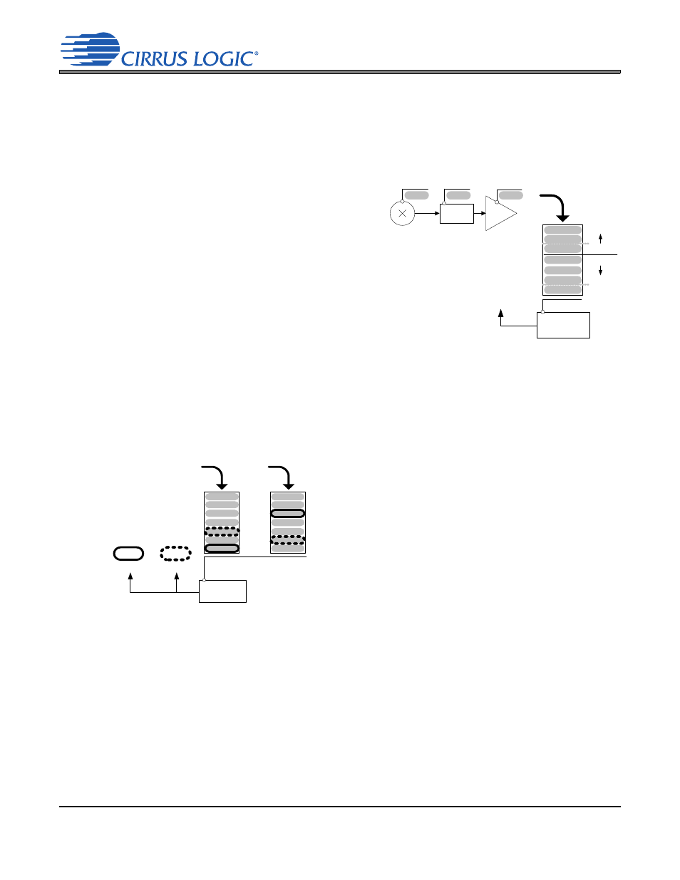
Effect of Volume Sum in A or B Path
Since amplifier channels A and B share the same supply, the
controller must consider the volume settings in the path of
both these channels before supplying the appropriate rail
voltage. For any of the three signal paths, the controller will
instruct the charge pump to supply ±VCP to the amplifiers
when the total gain/attenuation of either channel A or B ex-
ceeds the -10.5 dB threshold.
Conversely, the charge pump will supply ±VCP/2 only when
the total gain/attenuation of both channels A and B is less
than or equal to -10.5 dB.
-10.5 dB
Class H
Controller
+
+
=
±VCP/2
±VCP
HP/LINE Supply
Figure 22. Volume Sum Effects
-10.5 dB
case1
case2
Class H
Controller
HP/LINE Supply
Decision:
-10.5 dB
case2
case1
of A
Path
=
=
VCP
VCP/2
of B
Path
Case 1 Result
Case 2 Result
Figure 23. Channel/Amp Effect