Figure 18. alc operation, Figure 18.alc operation, Cs42l56 – Cirrus Logic CS42L56 User Manual
Page 35
DS851F2
35
CS42L56
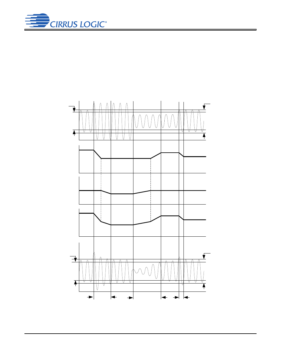
whenever a threshold violation occurs. It then modifies the signal level by adjusting the gain settings in
the PGA and ADC digital volume control accordingly.
, if the input signal level rises above the maximum threshold, the ALC first lowers
the PGA gain settings. It then decreases the ADC digital volume at a programmable “attack” rate and
maintains the resulting level below the maximum threshold. In contrast, if the input signal level falls below
the minimum threshold, the ALC first increases the ADC digital volume settings and then increases the
PGA gain settings at a programmable “release” rate. However, once an attack or release operation has
been performed on an input signal, the ALC does not change the PGA or the digital volume control set-
tings until the next threshold violation occurs.
Output
(after ALC)
Input (before ALC)
Total ALC
Response
ALCMAX[2:0]
ARATE[5:0]
below full scale
ALCMIN[2:0]
below full scale
ALCMIN[2:0]
below full scale
ALCMAX[2:0]
below full scale
PGA
Response
ADC Vol.
Cntrl.
Response
RRATE[5:0]
ARATE[5:0]
Figure 18. ALC Operation