Pulsafeeder Pulsar DLC User Manual
Page 84
79
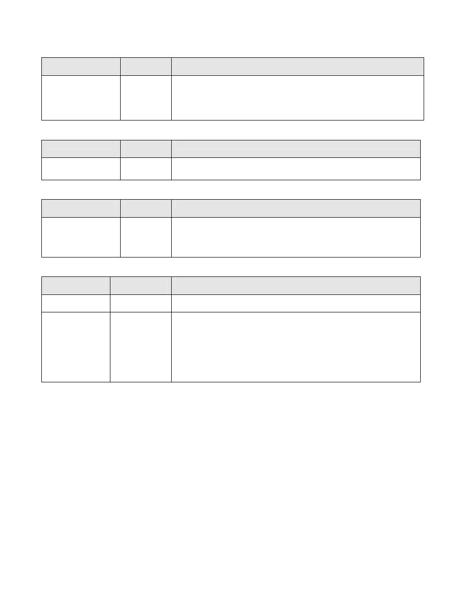
High Voltage Inputs
Inputs
Field Wiring
Location
Specification / Description
Line Power:
J1
Factory configured to one of the following:
115VAC
±
10%, 50/60 Hz, 10 Amp max
230VAC
±
10%, 50/60 Hz, 5 Amp max
Surge Protection: 7.4 Joules
Software protected against Over/Under voltage. (user selectable)
High Voltage Outputs
Inputs
Field Wiring
Location
Specification / Description
Alarm Relay
J2
Fused at 1 amp at rated Line voltage.
May be software configured as Normally Open or Normally Closed.
Serial Communications
Inputs
Field Wiring
Location
Specification / Description
RS–485
J7 & J8
Max Cable length: 1219 meters (4000 feet)
Max Address sites: 32
Use 120 ohm terminating resistors at both ends of network.
Isolation: 500 volts from ground and all other inputs and outputs.
Control Inputs
Control Inputs
Field Wiring
Location
Specification / Description
Tachometer
Sensor
J10 Pin 1 is VDC
J10 Pin 2 is Tach
Connection point for TURCK Sensor..
Motor
Thermostat
J10 Pin 3 is +
J10 Pin 4 is –
Dry Contact (Optically Isolated) – Do not apply powered signal.
Isolation: Not isolated from PULSAlarm or Digital Input, 500 volts from all
other inputs, outputs, and ground.
May be software configured as Normally Open or Normally Closed (default).
May be software configured to operate the Alarm Relay (default is YES).
May be software configured to turn the Pump Motor OFF
If MOTOR OFF is selected may optionally restart the Pump Motor when the
thermostat resets (default).