5 low voltage input connections, 3 alarm relay – Pulsafeeder Pulsar DLC User Manual
Page 17
12
5.4.3 Alarm Relay
The Alarm Relay is an output that is configured by the operator. Refer to Section 7 – General
Operation for specific instructions on how to activate the Alarm Relay. The Alarm Relay Load must
not exceed 1 Amp at rated voltage. Connect the Alarm load to the J2 terminal block labeled 'ALARM
RELAY OUT.' Use 22 AWG wire size. Make three connections: Neutral, Earth (ground) and Hot as
labeled.
5.5
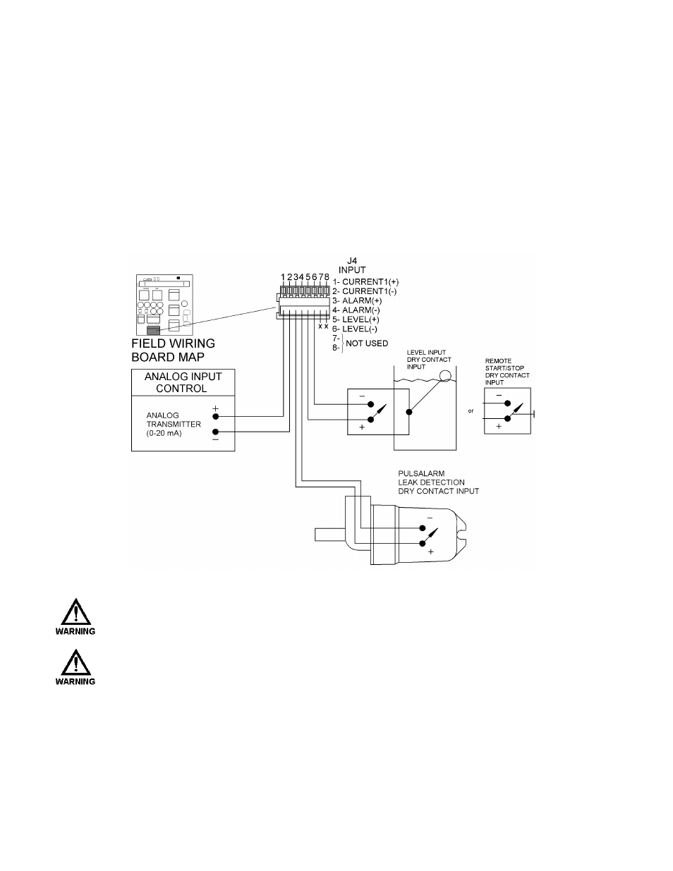
Low Voltage Input Connections
There are two types of Low Voltage inputs: Current (e.g., 4-20mA) and Dry Contact. The Low Voltage
Input connection block is labeled J4 'INPUT' (refer to Figure 5). It contains three pairs of inputs:
Current 1, Alarm and Level.
Figure 5 – Low Voltage Input
T
HE DRY CONTACT INPUTS ARE SELF
-
POWERED
. S
UPPLY ONLY A MECHANICAL SWITCH
CLOSURE TO ACTIVATE
. D
O NOT ATTACH EXTERNALLY POWERED CIRCUITRY
.
T
HE WIRE USED TO CONNECT
L
OW
V
OLTAGE
I
NPUTS
,
AND
S
ERIAL
C
OMMUNICATIONS SHOULD
BE RUN IN A CONDUIT SEPARATE FROM THE
H
IGH
V
OLTAGE
P
OWER
. D
O NOT COMBINE
H
IGH
V
OLTAGE
(
I
.
E
.,
GREATER THAN
100VAC)
LINES AND
L
OW
V
OLTAGE
(
I
.
E
.,
LESS THAN
32VDC)
LINES IN A COMMON CONDUIT
! F
AILURE TO COMPLY WILL RESULT IN ELECTRICAL
INTERFERENCE THAT MAY RESULT IN IMPROPER
(
AND POSSIBLY UNSAFE
)
OPERATION
.