Installing an at-cv5pnl3 blank slot cover – Allied Telesis AT-CV5000 User Manual
Page 93
AT-CV5000 Media Converter Chassis Installation Guide
93
Note
Always tighten the captive screws to secure the blank slot cover to
the chassis.
Installing an
AT-CV5PNL3
Blank Slot Cover
The AT-CV5PNL3 blank slot cover is designed to cover the unoccupied
expansion slot located in the rear of the AT-CV5000 chassis.
To install an AT-CV5PNL3 blank slot cover, perform the following
procedure:
1. Remove the AT-CV5PNL3 blank slot cover from its shipping package
and store the package in a safe place.
Note
You must use the original package if you need to return the unit to
Allied Telesis.
2. Align the back edge of the blank slot cover with the alignment guides
located inside the slot.
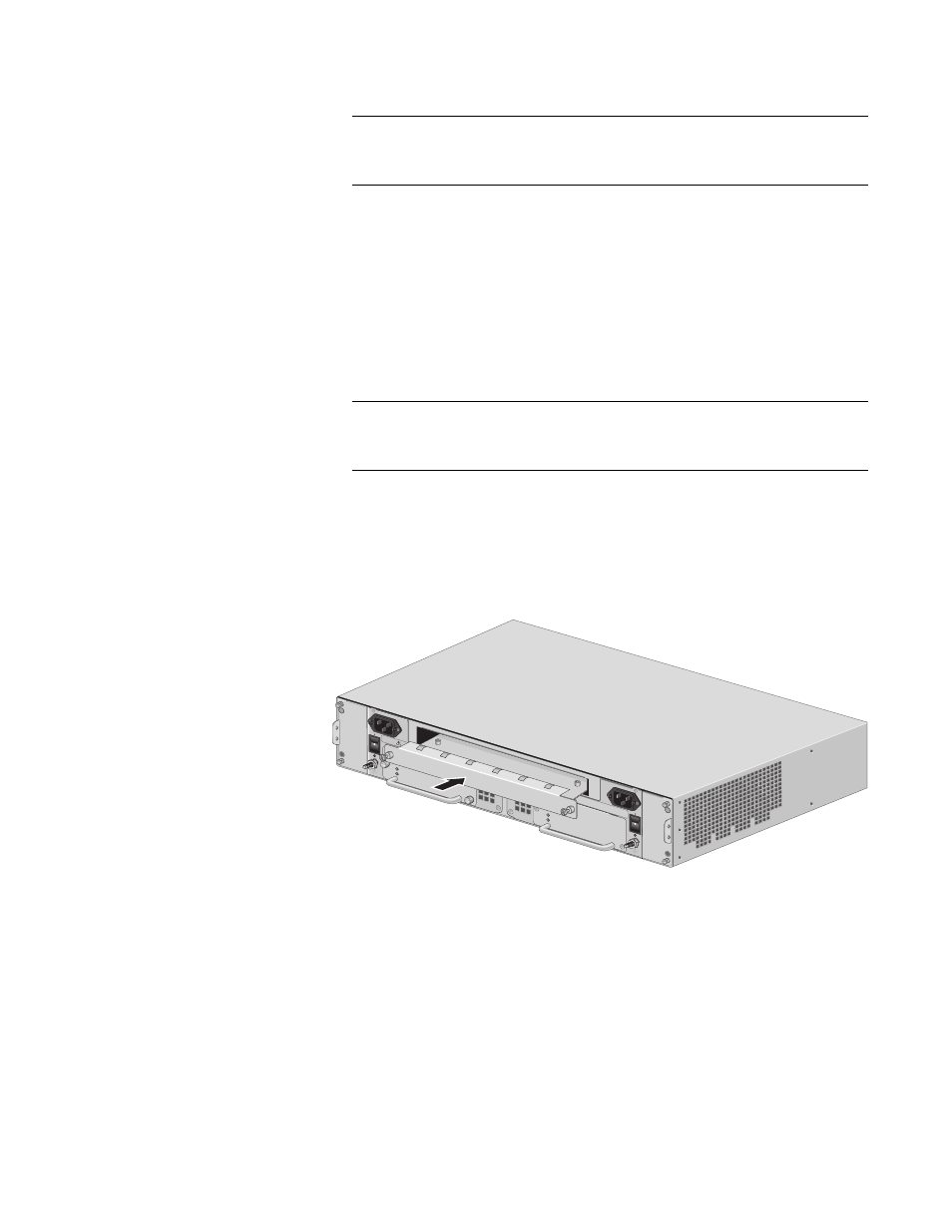
3. Slide the blank slot cover into the slot, as shown in Figure 70, until the
slot cover is flush with the front of the chassis.
Figure 70. Inserting an AT-CV5PNL3 Blank Slot Cover
AT-CV5PWR1
4
POWE
R
FAULT
AT-CV5PWR
AC
A
B
A
T
-CV5F
A
N
B
POWE
R
FAULT
A
T
-CVF
A
N
A
227
100-2
40VA
C
~
WA
RNIN
G
This u
nit m
ight h
ave m
ore th
an one
power
input. T
o
reduce
the ris
k of e
lectric
shock,
disco
nnect a
ll pow
er
100-240
VAC
~
WA
RNIN
G
This u
nit m
ight h
ave m
ore th
an one p
ower inpu
t. To
redu
ce the risk of electric sh
ock, discon
nect all p
ower
REAR EX
P. SL
OT