Powering on a dc powered chassis, Figure 41. dc terminal block – Allied Telesis AT-CV5000 User Manual
Page 64
Chapter 2: Installation
64
Powering On a DC Powered Chassis
This section describes how to power on a DC powered AT-CV5000
chassis. If your chassis is AC powered, see “Powering On an AC Powered
Chassis” on page 60. For information about how to install the power
supply, refer to “Installing an AT-PWR15 DC Power Supply” on page 84.
1. Make sure that the ON/OFF power switch is in the OFF position.
2. Locate the two DC terminal blocks, labeled A and B, on the rear panel
of the chassis.
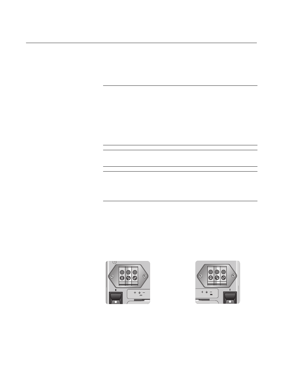
3. Starting from the left side of a terminal block, identify the positive,
power supply ground and negative terminals using the symbols
below the terminal block in Figure 41.
Figure 41. DC Terminal Block
Warning: As a safety precaution, install a circuit breaker with a
minimum value of 15 Amps between the equipment and the DC
power source.
Always connect the wires to the LAN equipment first before you
connect the wires to the circuit breaker. Do not work with HOT
feeds to avoid the danger of physical injury from electrical shock.
Always be sure that the circuit breaker is in the OFF position
before connecting the wires to the breaker.
E9
Warning: For centralized DC power connection, install only in a
restricted access area.
E23
A tray cable is required to connect the power source if the unit is
powered by centralized DC power. The tray cable must be a UL
listed Type TC tray cable and rated at 600 V and 90 degrees C,
with three conductors, minimum 14 AWG.
E24
A
40-60VDC INPUT
1136
250
40-60VDC
PWR A
PWR B