Wa rning – Allied Telesis AT-CV5000 User Manual
Page 87
AT-CV5000 Media Converter Chassis Installation Guide
87
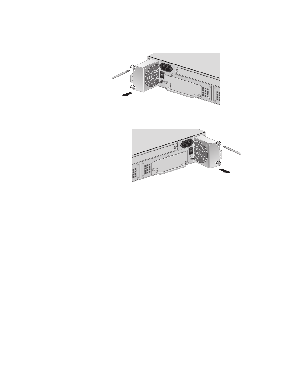
3. Pull the loosened screws to slide the fan out of the chassis, as shown
Figure 60. Removing an AT-CVFAN Module from Fan Slot A
Figure 61. Removing an AT-CVFAN Module from Fan Slot B
4. While you wait for the fan to spin down, unpack the new AT-CVFAN
module from the shipping package and store the packaging material in
a safe location.
Note
You must use the original shipping material if you need to return the
fan module to Allied Telesis.
5. Carefully remove the fan module from the chassis.
6. To install a new fan, do one of the following:
Caution
Avoid touching the fan blades.
AT-CV5PWRA
C
POWE
R
FAULT
AT-PW
R14
A
B
100-240
VAC
~
POWE
R
FAULT
A
A
T
-CVF
AN
204
100-2
40VAC
~
WARN
ING
This u
nit m
ight ha
ve more
than one po
wer input.
To
reduce the risk of electric s
hock, disconnect a
ll po
wer
AT-PWR14
AT-CV5PWRA
C
A
B
100
-240
VAC
~
FA
N
A
B
POW
ER
FAUL
T
A
T
-CVF
AN
205
100
-240
VAC
~
WA
RNING
This
unit
mig
ht h
ave m
ore t
han
one
pow
er in
put.
To
redu
ce th
e ris
k of
elec
tric
sho
ck, d
isco
nne
ct all
pow
er
- AT-GS908M (54 pages)
- AT-x230-10GP (80 pages)
- AT-GS950/48PS (64 pages)
- AT-GS950/10PS (386 pages)
- AT-GS950/16PS (386 pages)
- AT-GS950/48PS (386 pages)
- AT-9000 Series (258 pages)
- AT-9000 Series (1480 pages)
- IE200 Series (70 pages)
- AT-GS950/48 (60 pages)
- AT-GS950/48 (410 pages)
- AT-GS950/8 (52 pages)
- AT-GS950/48 (378 pages)
- SwitchBlade x8106 (322 pages)
- SwitchBlade x8112 (322 pages)
- SwitchBlade x8106 (240 pages)
- SwitchBlade x8112 (240 pages)
- AT-TQ Series (172 pages)
- AlliedWare Plus Operating System Version 5.4.4C (x310-26FT,x310-26FP,x310-50FT,x310-50FP) (2220 pages)
- FS970M Series (106 pages)
- 8100L Series (116 pages)
- 8100S Series (140 pages)
- x310 Series (116 pages)
- x310 Series (120 pages)
- AT-GS950/24 (404 pages)
- AT-GS950/24 (366 pages)
- AT-GS950/16 (44 pages)
- AT-GS950/16 (404 pages)
- AT-GS950/16 (364 pages)
- AT-GS950/8 (52 pages)
- AT-GS950/8 (404 pages)
- AT-GS950/8 (364 pages)
- AT-8100 Series (330 pages)
- AT-8100 Series (1962 pages)
- AT-FS970M Series (330 pages)
- AT-FS970M Series (1938 pages)
- SwitchBlade x3112 (294 pages)
- SwitchBlade x3106 (288 pages)
- SwitchBlade x3106 (260 pages)
- SwitchBlade x3112 (222 pages)
- AT-S95 CLI (AT-8000GS Series) (397 pages)
- AT-S94 CLI (AT-8000S Series) (402 pages)
- AT-IMC1000T/SFP (23 pages)
- AT-IMC1000TP/SFP (24 pages)
- AT-SBx3106WMB (44 pages)