Installing the at-cv5000 chassis in a rack, Chapter 2: installation 48, Lk at t x ml/sml fd/oam rdy lk at – Allied Telesis AT-CV5000 User Manual
Page 48
Chapter 2: Installation
48
Installing the AT-CV5000 Chassis in a Rack
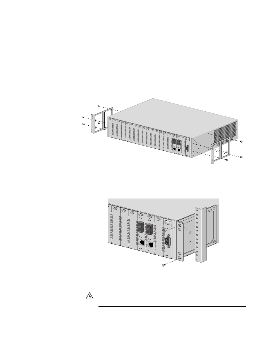
The chassis is shipped with two rack-mounting brackets. To mount the
chassis in a rack, perform the following procedure:
1. Place the chassis on a level, secure surface.
2. Attach the brackets to the sides of the chassis using four screws
(provided) on each side, as shown in Figure 18
Figure 18. Installing a Bracket to the Chassis
3. Mount the chassis in a 19-inch rack using appropriate screws (not
provided), as shown in Figure 19.
Figure 19. Mounting the AT-CV5000 Chassis in a 19-inch Rack
AT-CM
202
LK AT
T
X
ML/SML
FD/OAM
RDY
LK AT
AT-CM
202
LK AT
T
X
ML/SML
FD/OAM
RDY
LK AT
FAN1
PS1
RDY
RDY MS
TR FLT
RESET L
INE/SFM
PS-A P
S-B
FAN-A F
AN-B
A
T-CV5000
236
AT-CM202
LK
AT
T
X
ML/SML
FD/OAM
RDY
LK
AT
AT-CM202
LK
AT
T
X
ML/SML
FD/OAM
RDY
LK
AT
FAN1
PS1
RDY
AT-CV5LED
RDY MSTR FL
T
RESET LINE/SFM
PS-A PS-B
FAN-A F
AN-B
237
Caution: Air vents must not be blocked and must have free
access to the room ambient air for cooling.
E6
- AT-GS908M (54 pages)
- AT-x230-10GP (80 pages)
- AT-GS950/48PS (64 pages)
- AT-GS950/10PS (386 pages)
- AT-GS950/16PS (386 pages)
- AT-GS950/48PS (386 pages)
- AT-9000 Series (258 pages)
- AT-9000 Series (1480 pages)
- IE200 Series (70 pages)
- AT-GS950/48 (60 pages)
- AT-GS950/48 (410 pages)
- AT-GS950/8 (52 pages)
- AT-GS950/48 (378 pages)
- SwitchBlade x8106 (322 pages)
- SwitchBlade x8112 (322 pages)
- SwitchBlade x8106 (240 pages)
- SwitchBlade x8112 (240 pages)
- AT-TQ Series (172 pages)
- AlliedWare Plus Operating System Version 5.4.4C (x310-26FT,x310-26FP,x310-50FT,x310-50FP) (2220 pages)
- FS970M Series (106 pages)
- 8100L Series (116 pages)
- 8100S Series (140 pages)
- x310 Series (116 pages)
- x310 Series (120 pages)
- AT-GS950/24 (404 pages)
- AT-GS950/24 (366 pages)
- AT-GS950/16 (44 pages)
- AT-GS950/16 (404 pages)
- AT-GS950/16 (364 pages)
- AT-GS950/8 (52 pages)
- AT-GS950/8 (404 pages)
- AT-GS950/8 (364 pages)
- AT-8100 Series (330 pages)
- AT-8100 Series (1962 pages)
- AT-FS970M Series (330 pages)
- AT-FS970M Series (1938 pages)
- SwitchBlade x3112 (294 pages)
- SwitchBlade x3106 (288 pages)
- SwitchBlade x3106 (260 pages)
- SwitchBlade x3112 (222 pages)
- AT-S95 CLI (AT-8000GS Series) (397 pages)
- AT-S94 CLI (AT-8000S Series) (402 pages)
- AT-IMC1000T/SFP (23 pages)
- AT-IMC1000TP/SFP (24 pages)
- AT-SBx3106WMB (44 pages)