Figure 65, Wa rning – Allied Telesis AT-CV5000 User Manual
Page 89
AT-CV5000 Media Converter Chassis Installation Guide
89
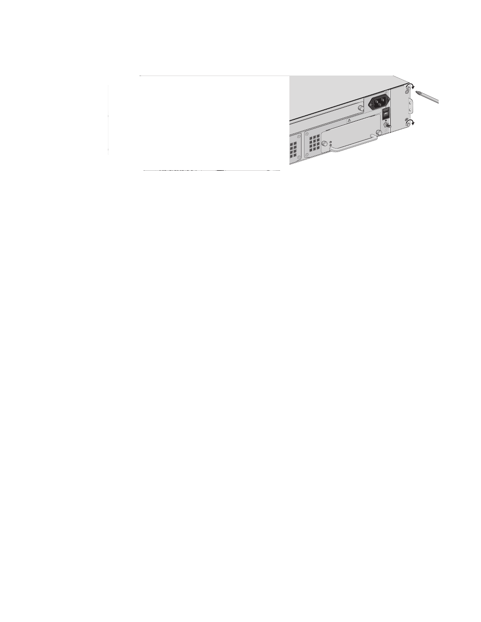
Figure 65. Tightening the Screws on the AT-CVFAN Module in Slot B
To power on the chassis, proceed to the procedure described in
“Powering On an AC Powered Chassis” on page 60 or “Powering On a
DC Powered Chassis” on page 64.
When the connection is established, the appropriate fan LED (FAN-A
or FAN-B) on the LED interface card should be green. If the LED is
OFF, refer to “Troubleshooting” on page 95 for instructions.
AT-PWR14
R
AT-CV5PWRA
C
A
B
100
-240
VAC
~
5F
AN
A
POW
ER
FAUL
T
A
T
-CVF
AN
B
100
-240
VAC
~
WA
RNING
This
unit
mig
ht h
ave m
ore
than
one
pow
er in
put.
To
redu
ce th
e ris
k of
elec
tric s
hoc
k, dis
con
nect
all p
owe
r
See also other documents in the category Allied Telesis Computer hardware:
- AT-GS908M (54 pages)
- AT-x230-10GP (80 pages)
- AT-GS950/48PS (64 pages)
- AT-GS950/10PS (386 pages)
- AT-GS950/16PS (386 pages)
- AT-GS950/48PS (386 pages)
- AT-9000 Series (258 pages)
- AT-9000 Series (1480 pages)
- IE200 Series (70 pages)
- AT-GS950/8 (52 pages)
- AT-GS950/48 (378 pages)
- AT-GS950/48 (60 pages)
- AT-GS950/48 (410 pages)
- SwitchBlade x8106 (322 pages)
- SwitchBlade x8112 (322 pages)
- SwitchBlade x8106 (240 pages)
- SwitchBlade x8112 (240 pages)
- AT-TQ Series (172 pages)
- AlliedWare Plus Operating System Version 5.4.4C (x310-26FT,x310-26FP,x310-50FT,x310-50FP) (2220 pages)
- FS970M Series (106 pages)
- 8100S Series (140 pages)
- 8100L Series (116 pages)
- x310 Series (116 pages)
- x310 Series (120 pages)
- AT-GS950/24 (366 pages)
- AT-GS950/16 (44 pages)
- AT-GS950/24 (404 pages)
- AT-GS950/16 (404 pages)
- AT-GS950/16 (364 pages)
- AT-GS950/8 (404 pages)
- AT-GS950/8 (364 pages)
- AT-GS950/8 (52 pages)
- AT-8100 Series (330 pages)
- AT-8100 Series (1962 pages)
- AT-FS970M Series (1938 pages)
- AT-FS970M Series (330 pages)
- SwitchBlade x3106 (288 pages)
- SwitchBlade x3112 (294 pages)
- SwitchBlade x3106 (260 pages)
- SwitchBlade x3112 (222 pages)
- AT-S95 CLI (AT-8000GS Series) (397 pages)
- AT-S94 CLI (AT-8000S Series) (402 pages)
- AT-IMC1000T/SFP (23 pages)
- AT-IMC1000TP/SFP (24 pages)
- AT-SBx3106WMB (44 pages)