Grounding the at-cv5000 chassis, One ground lug (two are provided), Frame ground connectors – Allied Telesis AT-CV5000 User Manual
Page 50: Chapter 2: installation 50
Chapter 2: Installation
50
Grounding the AT-CV5000 Chassis
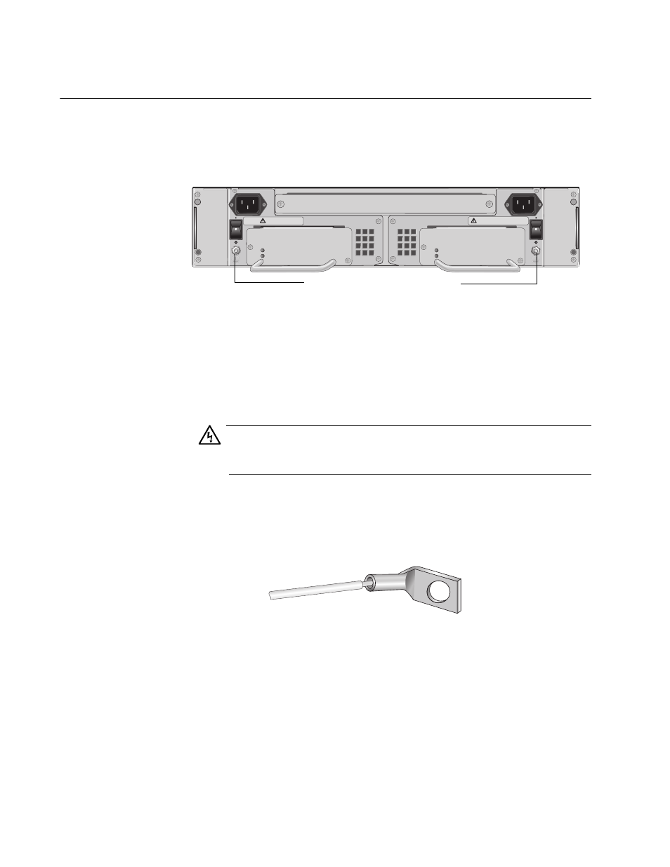
To ensure the safe and proper operation of your AT-CV5000 chassis, you
must ground the unit to a ground point using either of the frame ground
connectors on the rear panel, as shown in Figure 20.
Figure 20. Frame Ground Connectors
Grounding the chassis requires the following items:
One ground lug (two are provided)
One 12 AWG stranded wire or 14 AWG solid wire (not provided)
Crimping tool (not provided)
Warning
When installing this equipment, always ensure that the frame
ground connection is installed first and disconnected last.
E11
To attach the frame ground, perform the following procedure:
1. Use a crimping tool to affix the ground lug to one end of the 12 AWG
stranded or 14 AWG solid ground wire, as shown in Figure 21.
Figure 21. Connecting the Wire to the Ground Lug
2. Remove the lock nut from either frame ground stud on the rear panel
of the AT-CV5000 chassis.
3. Place the ground lug on the frame ground stud where you removed the
lock nut.
A
A
T
-CVF
A
N
A
A
T
-CVF
A
N
B
1163
REAR EXP. SLOT
100-240VAC
~
WARNING
This unit might have more than one power input. To
reduce the risk of electric shock, disconnect all power
inputs before servicing unit.
B
100-240VAC
~
WARNING
This unit might have more than one power input. To
reduce the risk of electric shock, disconnect all power
inputs before servicing unit.
POWER
FAULT
AT-PWR14
AT-PWR14
POWER
FAULT
Frame Ground Connectors
707