Chapter 2: installation 46, At-pwr1 4, Bracket – Allied Telesis AT-CV5000 User Manual
Page 46
Chapter 2: Installation
46
Installing the Power Cord Retaining Clip (AC Powered Chassis Only)
To install the power cord retaining clip on an AT-CV5000 chassis with an
AT-PWR14 AC power supply, perform the following procedure:
1. Locate the power cord retaining clip which is shown in Figure 14.
Figure 14. Power Cord Retaining Clip
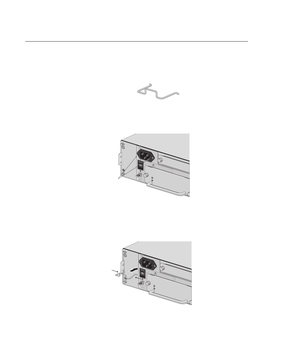
2. Locate the retaining bracket on each side of the AC power connector
on the rear of the chassis, as shown in Figure 15.
Figure 15. Power Cord Retaining Bracket
3. With the “u” of the clip facing up, press the sides of the clip toward the
center and insert the short ends into the holes in the retaining bracket,
as shown in Figure 16.
Figure 16. Inserting the Retaining Clip into the Retaining Bracket
POWER
FAULT
AT-PWR1
4
A
A
T
-CVF
AN
A
100-240V
AC
~
WARNING
This u
nit m
ight h
ave m
ore th
an one
power in
put. To
reduce
the ris
k of e
lectric
shock
, disco
nnect a
ll powe
r
inputs
before
servic
ing unit.
275
Bracket
POWER
FAULT
AT-PWR1
4
A
A
T
-CVF
AN
A
100-240V
AC
~
WARNING
This u
nit m
ight h
ave m
ore th
an one
power in
put. To
reduce
the ris
k of e
lectric
shock
, disco
nnect a
ll powe
r
inputs
before
servic
ing unit.
276