Figure 40. on/off power switch in on position, Power switches to on position pwr a pwr b, Chapter 2: installation 62 – Allied Telesis AT-CV5000 User Manual
Page 62
Chapter 2: Installation
62
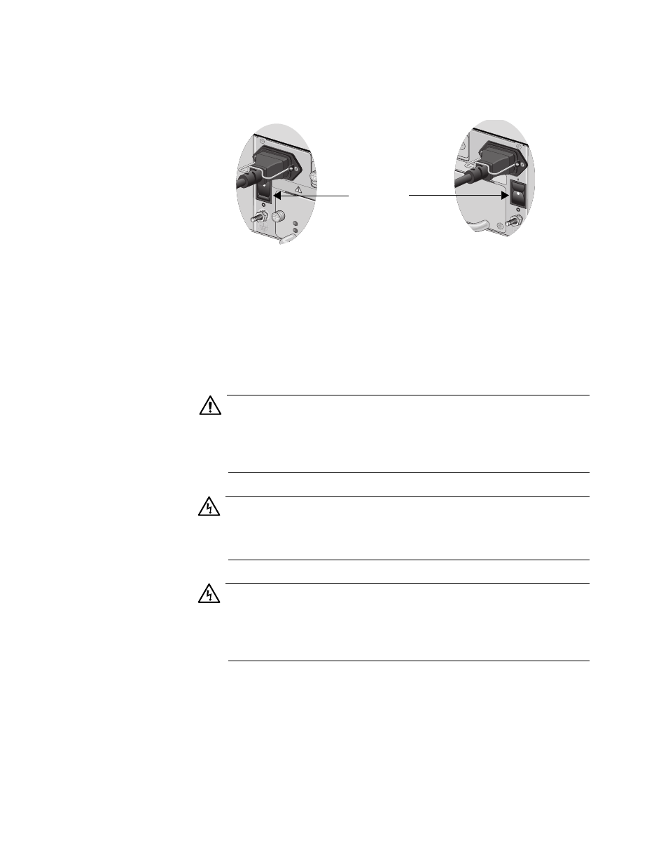
6. Turn the ON/OFF power switch of the installed power supply module
to the ON position, as shown in Figure 40.
Figure 40. ON/OFF Power Switch in ON Position
7. Plug the other end of the power adapter to a power outlet.
If you purchased a second AT-PWR14 AC power module, repeat this
procedure to install the additional module.
Refer to “Technical Specifications” on page 101 for power
requirements.
Caution
To further protect the AT-CV5000 chassis, connect each AC power
cord to power sources that are operating on different power circuits.
This arrangement protects the chassis from a power loss if one of
the power circuits fails.
Warning
This unit might have more than one power source. To reduce the
risk of electric shock, disconnect all power cords before servicing the
unit. E30
Warning
Class I Equipment. This equipment must be earthed. The power
plug must be connected to a properly wired earth ground socket
outlet. An improperly wired socket outlet could place hazardous
voltages on accessible metal parts. E4
8. Check that the POWER LED on the AT-PWR14 AC power module is
green. If the POWER LED is OFF or the FAULT LED is ON, refer to
“Troubleshooting” on page 95 for instructions.
The chassis is now ready for network operations.
No further installation steps are required if you do not need to change the
518
POWE
R
FAULT
A
100-240
VAC
~
WARNING
This unit might h
reduce the risk o
inputs bef
ore ser
Power Switches
to ON
Position
PWR A
PWR B
AC
B
100-2
40VA
C
~
NG
migh
t have
more th
an one
power in
put. To
he risk
of elec
tric sh
ock, d
isconnec
t all po
wer
efore s
ervicin
g unit.
1135