Power supplies, At-pwr14 ac module – Allied Telesis AT-CV5000 User Manual
Page 31
AT-CV5000 Media Converter Chassis Installation Guide
31
Power Supplies
The AT-CV5000 chassis is shipped with two rear slots designated for the
power supplies. Two power supply options are available:
AT-PWR14 AC module
AT-PWR15 DC module
Caution
The AT-CV5000 Media Converter chassis can contain two power
supplies of the same type (AC or DC) or a combination of the two
versions with the same power ratings. Make sure not to mix power
supplies with different power ratings in the same chassis.
For information on the power supply module, refer to the
documentation that is shipped with the module.
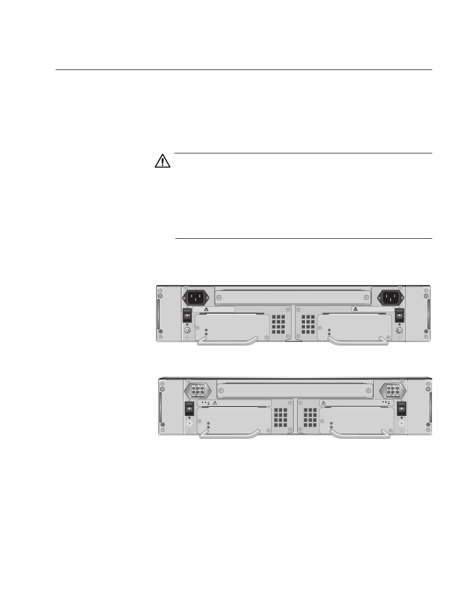
An AC powered chassis is shown in Figure 8 and a DC-powered chassis is
shown in Figure 9.
Figure 8. AT-CV5000 AC Powered Chassis
Figure 9. AT-CV5000 DC Powered Chassis
When two power supplies are installed, one provides full power to the
chassis and the one of them works in standby mode. If one power supply
fails, the remaining power supply provides all the power to the system,
preventing a system failure.
A
A
T
-CVF
A
N
A
A
T
-CVF
A
N
B
1163
REAR EXP. SLOT
100-240VAC
~
WARNING
This unit might have more than one power input. To
reduce the risk of electric shock, disconnect all power
inputs before servicing unit.
B
100-240VAC
~
WARNING
This unit might have more than one power input. To
reduce the risk of electric shock, disconnect all power
inputs before servicing unit.
POWER
FAULT
AT-PWR14
AT-PWR14
POWER
FAULT
POWER
FAULT
AT-PWR15
A
B
A
T
-CVF
A
N
A
A
T
-CVF
A
N
B
AT-PWR15
POWER
FAULT
40-60VDC
WARNING
This unit might have more than one power input. To
reduce the risk of electric shock, disconnect all power
FOR CENTRALIZED DC POWER
CONNECTION, INSTALL ONLY IN
A RESTRICTED AREA.
40-60VDC
WARNING
This unit might have more than one power input. To
reduce the risk of electric shock, disconnect all power
FOR CENTRALIZED DC POWER
CONNECTION, INSTALL ONLY IN
A RESTRICTED AREA.
1162
REAR EXP. SLOT