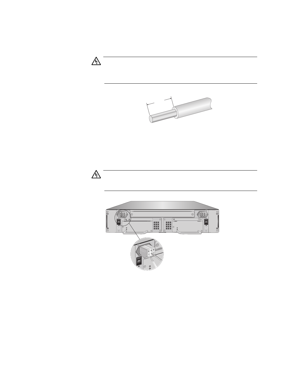
Figure 42. stripped wire, Pwr a, 60vdc warning – Allied Telesis AT-CV5000 User Manual
Page 65
AT-CV5000 Media Converter Chassis Installation Guide
65
4. With a 14-gauge wire-stripping tool, strip the three wires in the tray
cable coming from the DC input power source to 8mm
± 1mm (0.31 in.,
± 0.039 in.), as shown in Figure 42 on page 65.
Warning
Do not strip more than the recommended amount of wire. Stripping
more than the recommended amount can create a safety hazard by
leaving exposed wire on the terminal block after installation. E10
Figure 42. Stripped Wire
5. Connect the power supply ground wire into the middle of the three
terminals; this is the terminal marked with the ground symbol. Inserting
the wire into the terminal and tightening the connection with a flathead
screwdriver, as shown in Figure 43.
Warning
When installing this equipment, always ensure that the power supply
ground connection is installed first and disconnected last. E11
8mm ±1mm
(0.31in. ±0.039in.)
POWER
FAULT
AT-PWR15
A
B
A
T
-CVF
AN
A
AT
-C
V
F
A
N
B
AT-PWR15
POWER
FAULT
40-60VDC
WARNING
This unit might have more than one power input. To
reduce the risk of electric shock, disconnect all power
FOR CENTRALIZED DC POWER
CONNECTION, INSTALL ONLY IN
A RESTRICTED AREA.
40-60VDC
WARNING
This unit might have more than one power input. To
reduce the risk of electric shock, disconnect all power
FOR CENTRALIZED DC POWER
CONNECTION, INSTALL ONLY IN
A RESTRICTED AREA.
1124
REAR EXP. SLOT
POW
ER
FAUL
T
AT-P
A
40-6
0VD
C
WA
RNIN
G
This unit
might h
ave
more
t
reduce the
risk o
f elec
tric s
PWR A