Pwr a pwr b, 2 40va c – Allied Telesis AT-CV5000 User Manual
Page 83
AT-CV5000 Media Converter Chassis Installation Guide
83
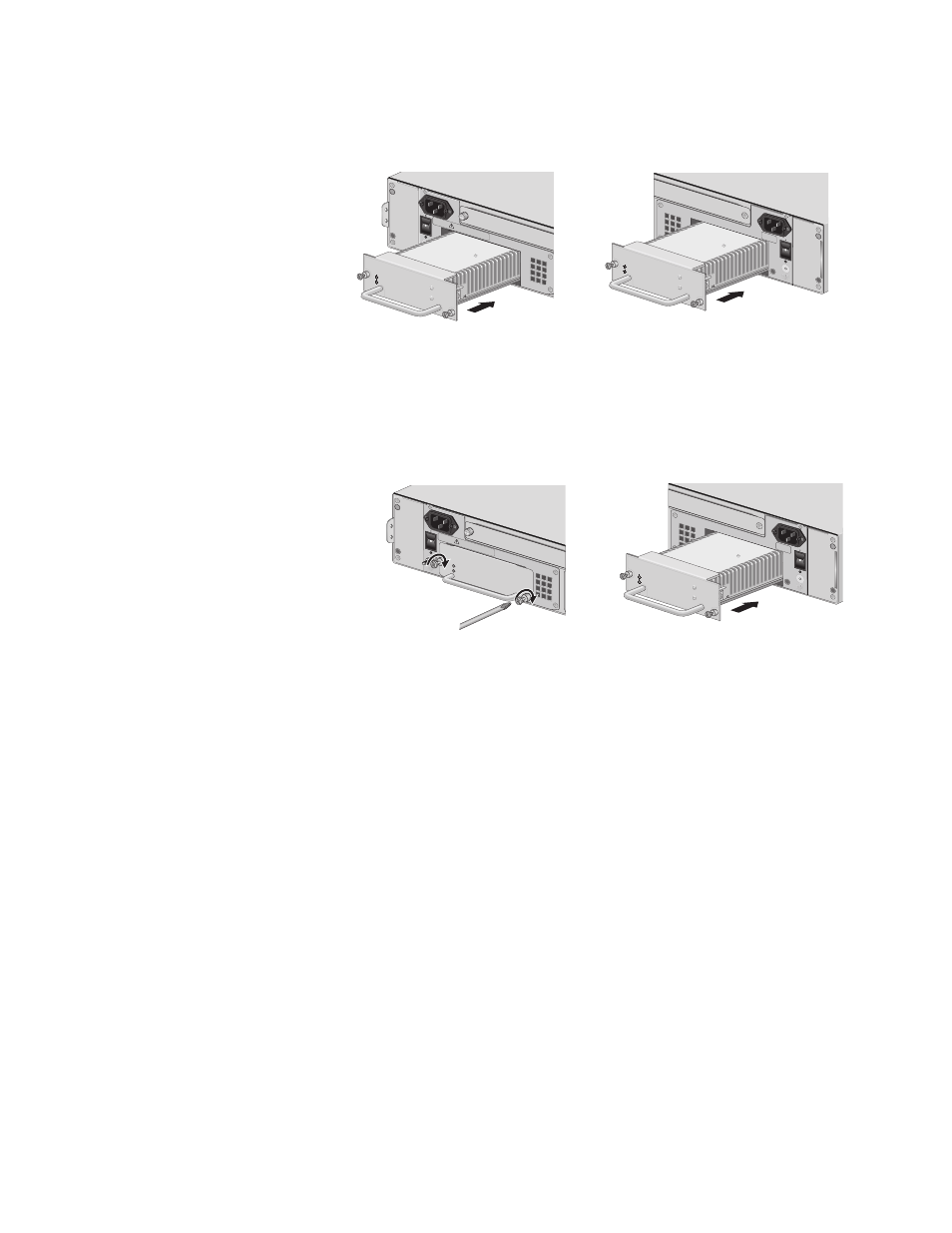
5. Slide the AT-PWR14 power supply into the selected slot, as shown in
Figure 56, until the module is flush with the front of the chassis.
Figure 56. Inserting the AT-PWR14 AC Power Supply
6. Secure the AT-PWR14 AC power supply to the AT-CV5000 chassis by
using a Phillips screwdriver to tighten the captive screws, as shown in
Figure 57.
Figure 57. Securing the AT-PWR14 AC Power Supply
For information about powering on an AC-powered chassis and starting a
management session, refer to “Powering On an AC Powered Chassis” on
page 60.
209
A
100-2
40VA
C
~
POWER
FAULT
AT-PW
R14
A
WARN
ING
This un
it migh
t have m
ore tha
n one p
ower in
put. To
reduce
the ris
k of ele
ctric sh
ock, dis
connec
t all po
wer
B
100-2
40VA
C
~
A
T
-CV5F
A
N
B
1129
POW
ER
FAULT
AT-PW
R14
PWR A
PWR B
A
100-2
40VA
C
~
POWER
FAULT
AT-PWR1
4
A
A
T
-CVF
AN
100-2
40VA
C
~
WA
RNIN
G
This unit might h
ave more than one p
ower input
. To reduce the
risk of electric sho
ck, disconnect all p
ower inputs be
fore
servicing unit.
212
PWR A
PWR B
B
100-2
40VA
C
~
A
T
-CV5F
A
N
B
1129
POW
ER
FAUL
T
AT-PW
R14