Pwr b, Pwr a – Allied Telesis AT-CV5000 User Manual
Page 85
AT-CV5000 Media Converter Chassis Installation Guide
85
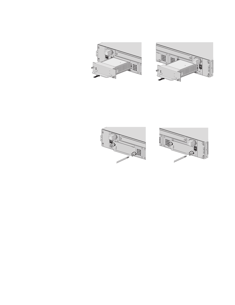
5. Slide the AT-PWR15 DC power supply into the selected slot, as shown
in Figure 58, until the module is flush with the front of the chassis.
Figure 58. Inserting the AT-PWR15 DC Power Supply
6. Secure the AT-PWR15 module to the AT-CV5000 chassis by using a
Phillips screwdriver to tighten the captive screws, as shown in
Figure 59.
Figure 59. Securing the AT-PWR15 DC Power Supply
For information about powering on an DC-powered chassis and starting a
management session, refer to “Powering On a DC Powered Chassis” on
page 64.
PWR A
B
AT-CV5FAN
B
WAR
NING
This u
nit m
ight h
ave m
ore th
an one
power
input. T
o
reduce
the ris
k of e
lectric s
hock, di
sconne
ct all p
ower
inputs
before
servic
ing un
it.
FOR C
ENTR
ALIZ
ED D
C PO
WER
CONN
ECTIO
N, INS
TALL
ONLY
IN
A RE
STRIC
TED A
REA.
POWER
FAULT
AT-PW
R15
216
A
A
40-60
VDC
WA
RNIN
G
This u
nit mig
ht hav
e more
than o
ne pow
er inpu
t. To
reduce
the ris
k of ele
ctric s
hock, d
isconn
ect all p
ower
inputs
before
servic
ing un
it.
FOR C
ENTR
ALIZE
D DC
POW
ER
CON
NECT
ION, IN
STAL
L ON
LY IN
A RE
STRIC
TED A
REA.
1225
POW
ER
FAULT
AT-PW
R15
PWR B
PWR B
B
AT-CV5FAN
B
POWE
R
FAULT
AT-PWR1
5
WAR
NING
This u
nit m
ight h
ave m
ore th
an one
power
input. T
o
reduce
the ris
k of ele
ctric s
hock, d
isconn
ect all p
ower
inputs
before
servic
ing un
it.
FOR C
ENTR
ALIZE
D DC
POW
ER
CONN
ECTIO
N, INS
TALL
ONLY
IN
A RE
STRIC
TED A
REA.
220
A
A
40-60
VDC
WA
RNIN
G
This u
nit mig
ht hav
e more
than o
ne pow
er inpu
t. To
reduce
the ris
k of ele
ctric s
hock, d
isconn
ect all p
ower
inputs
before
servic
ing un
it.
FOR C
ENTR
ALIZ
ED D
C POW
ER
CON
NECT
ION, IN
STAL
L ON
LY IN
A RE
STRIC
TED A
REA.
1227
POWE
R
FAULT
AT-PWR1
5
PWR A