2 40va c, 2 40vac, 240 vac – Allied Telesis AT-CV5000 User Manual
Page 88
Chapter 3: Working with Line Cards and other Modules
88
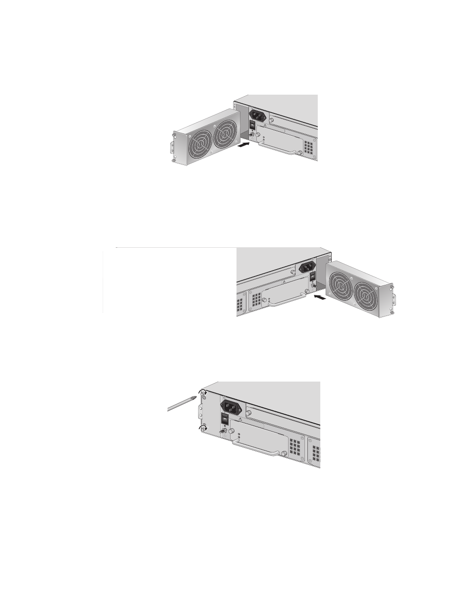
a. To install a new fan in slot A, turn the fan so that the handle is on
the left and slide the new fan module into the fan slot, as shown in
Figure 62.
Figure 62. Inserting an AT-CVFAN Module into Fan Slot A
b. To install a new fan in slot B, turn the fan so that the handle is on
the right and slide the new fan module into the fan slot, as shown in
Figure 63, until the front of the fan module is flush with the front of
the chassis.
Figure 63. Inserting an AT-CVFAN Module into Fan Slot B
7. Tighten the two captive screws on the fan module, as shown in
Figure 64. Tightening the Screws on the AT-CVFAN Module in Slot A.
AT-CV5PWR
AC
POWE
R
FAULT
AT-PWR14
A
B
100-2
40VA
C
~
A
T
-CV5
FA
B
POWE
R
FAUL
T
A
A
T
-CVF
A
N
202
100-2
40VAC
~
WAR
NING
This u
nit mig
ht hav
e more
than o
ne pow
er inpu
t. To re
duce
the ris
k of ele
ctric s
hock, d
isconn
ect all p
ower in
puts
before
servic
ing un
it.
AT-PWR1
4
POW
ER
FAULT
AT-CV5PWRA
C
A
B
100-240
VAC
~
T-
CV5F
A
N
A
B
POW
ER
FAUL
T
A
T
-CVF
A
N
203
100
-240
VAC
~
WARNING
This
uni
t mi
ght
have
mo
re th
an o
ne p
owe
r inp
ut. T
o
redu
ce th
e ris
k of
elec
tric
sho
ck, d
isco
nne
ct al
l po
wer
inpu
ts b
efor
e se
rvic
ing
unit
.
AT-CV5PW
RAC
POWE
R
FAULT
AT-PW
R14
A
B
100-240
VAC
~
A
T
-CV5F
A
B
POWE
R
FAULT
A
T
-CVF
AN
A
206
100-2
40VAC
~
WARN
ING
This unit might ha
ve more tha
n one po
wer input.
To
reduce the risk of electric
shoc
k, disconnect all po
wer