Figure 30: rack mounting hole locations – Allied Telesis SwitchBlade x8106 User Manual
Page 75
SwitchBlade x8106 Chassis Switch Installation Guide
75
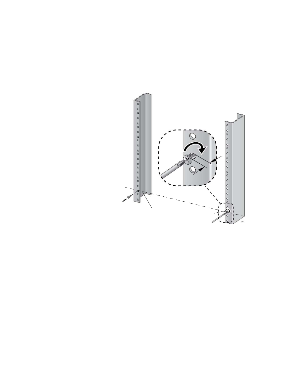
3. Identify the lowest 1/2” screw hole pattern on the rack mounting rails
within the space reserved for the AT-SBx8106 Chassis.
4. Install one rack mount screw in each vertical rail, at the same height in
the top screw hole of the lowest 1/2” hole pattern, as shown in
Figure 30. Do not fully tighten the screws at this time. The screw heads
should protrude from the rack approximately 6.4 mm (.25 in). The
screws are used to support the chassis while you secure it to the rack.
Figure 30. Rack Mounting Hole Locations
5. After installing the two screws in the equipment rack, go to “Unpacking
the AT-SBx8106 Chassis” on page 76.
6.4 mm (.25 in)
Screw head
Top screw hole of the lowest 1/2” hole pattern
away from rack
- AT-GS908M (54 pages)
- AT-x230-10GP (80 pages)
- AT-GS950/48PS (64 pages)
- AT-GS950/10PS (386 pages)
- AT-GS950/16PS (386 pages)
- AT-GS950/48PS (386 pages)
- AT-9000 Series (258 pages)
- AT-9000 Series (1480 pages)
- IE200 Series (70 pages)
- AT-GS950/48 (410 pages)
- AT-GS950/8 (52 pages)
- AT-GS950/48 (378 pages)
- AT-GS950/48 (60 pages)
- SwitchBlade x8106 (322 pages)
- SwitchBlade x8112 (322 pages)
- SwitchBlade x8112 (240 pages)
- AT-TQ Series (172 pages)
- AlliedWare Plus Operating System Version 5.4.4C (x310-26FT,x310-26FP,x310-50FT,x310-50FP) (2220 pages)
- FS970M Series (106 pages)
- 8100L Series (116 pages)
- 8100S Series (140 pages)
- x310 Series (116 pages)
- x310 Series (120 pages)
- AT-GS950/24 (404 pages)
- AT-GS950/24 (366 pages)
- AT-GS950/16 (44 pages)
- AT-GS950/16 (404 pages)
- AT-GS950/16 (364 pages)
- AT-GS950/8 (404 pages)
- AT-GS950/8 (364 pages)
- AT-GS950/8 (52 pages)
- AT-8100 Series (330 pages)
- AT-8100 Series (1962 pages)
- AT-FS970M Series (330 pages)
- AT-FS970M Series (1938 pages)
- SwitchBlade x3106 (288 pages)
- SwitchBlade x3112 (294 pages)
- SwitchBlade x3106 (260 pages)
- SwitchBlade x3112 (222 pages)
- AT-S95 CLI (AT-8000GS Series) (397 pages)
- AT-S94 CLI (AT-8000S Series) (402 pages)
- AT-IMC1000T/SFP (23 pages)
- AT-IMC1000TP/SFP (24 pages)
- AT-SBx3106WMB (44 pages)