Coax cables – Ag Leader GeoSteer Installation Manual User Manual
Page 50
Coax Cables
40
GeoSteer System
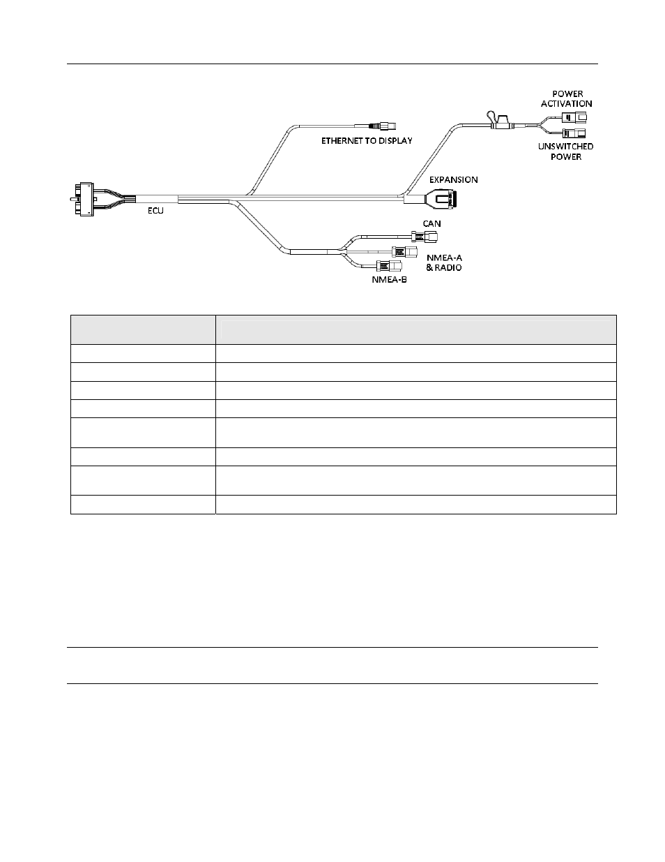
Figure 8-14 GeoSteer Main Cable Harness
Table 8-1
GeoSteer Main Cable Harness Connections
GeoSteer Main Cable Harness
Connector
Connected to
ECU
GeoSteer Control Unit 30-Pin on Left Side
ETHERNET TO DISPLAY
Display Ethernet Port (RJ-45)
UNSWITCHED POWER
12 Volt Power Source from Battery
POWER ACTIVATION
Power Activation Signal from Display
EXPANSION
Expansion Devices such as GeoDock Radio Modems or OmniSTAR demodulator, Secondary
CAN Bus Connection, SA Module, etc.
CAN
Primary CAN Bus Connection on Vehicle
NMEA-A & RADIO
Third Party Device Requiring NMEA out and/or External Radio Modem Providing Correction
Source Data
NMEA-B
Third Party Device Requiring NMEA out
Coax Cables
The GeoSteer Control Unit is connected to the GeoDock with one or two coax cables depending on the options that have been
ordered. One of the coax cables connects the TNC connector on the GeoDock GPS antenna to the TNC connector on the
GeoSteer Control Unit. If a cell modem is installed on the GeoSteer Control Unit, the second coax cable connects the Reverse
TNC connector from the Cell Modem Antenna on the GeoDock to the SMA connector on the GeoSteer Control Unit. Figure
8-15 and Figure 8-16 show the connectors on the GeoSteer Control Unit and GeoDock that need to be connected.
Note: Do not use a tool to tighten the coax connectors on either end of the coax cable. Hand tighten only or the connectors
could be damaged.