Cat valve installation example – Ag Leader GeoSteer Installation Manual User Manual
Page 45
Cable Diagram Examples
Hardware
Installation
Guide
35
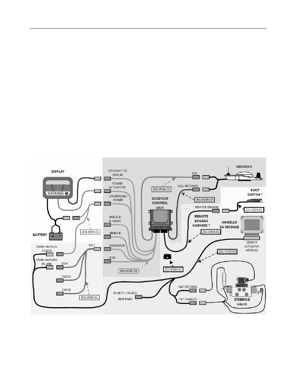
CAT Valve Installation Example
• Cell Antenna Coax Cable (PN 201-0539-02) is not required if not using a Cell Modem.
• Foot Switch (PN 201-0376-01) is an optional accessory component.
• Remote Engage Harness (PN 201-0563-01) is an optional accessory component required to allow CAT vehicle to use the
optional Foot Switch. The Remote Engage port from the SA Module Harness is not used.
• If the Remote Engage Harness is not installed, the Dummy Plug (201-0566-01) must be installed on the Vehicle port of the
GeoSteer Control Unit to protect the connectors.
• GeoSteer can be connected to multiple models of Displays. Refer to the Display User Manual for more detailed instructions
on how to connect the GeoSteer to the Display data and power ports.
• Component definitions
• DISPLAY – The Display that is connected to the GeoSteer system
• BATTERY – The battery terminals for the power source for the GeoSteer system and Display
• GEOSTEER CONTROL UNIT – The GeoSteer Control Unit
• GEODOCK – The GeoDock unit mounted on the roof
• FOOT SWITCH* – The optional Foot Switch that can be used for Remote Engage (not necessary for installation)
• REMOTE ENGAGE HARNESS* - The optional harness to connect the GeoSteer Control Unit to Foot Switch
• STEERING VALVE – The CAT Valve used to steer the vehicle
• WHEELED SA MODULE – Allows GeoSteer Control Unit to command the CAT Steering Valve via CAT SA Module
Harness and Expansion Adapter Harness
Figure 8-9 CAT Valve Installation Example