Geosteer main cable harness – Ag Leader GeoSteer Installation Manual User Manual
Page 49
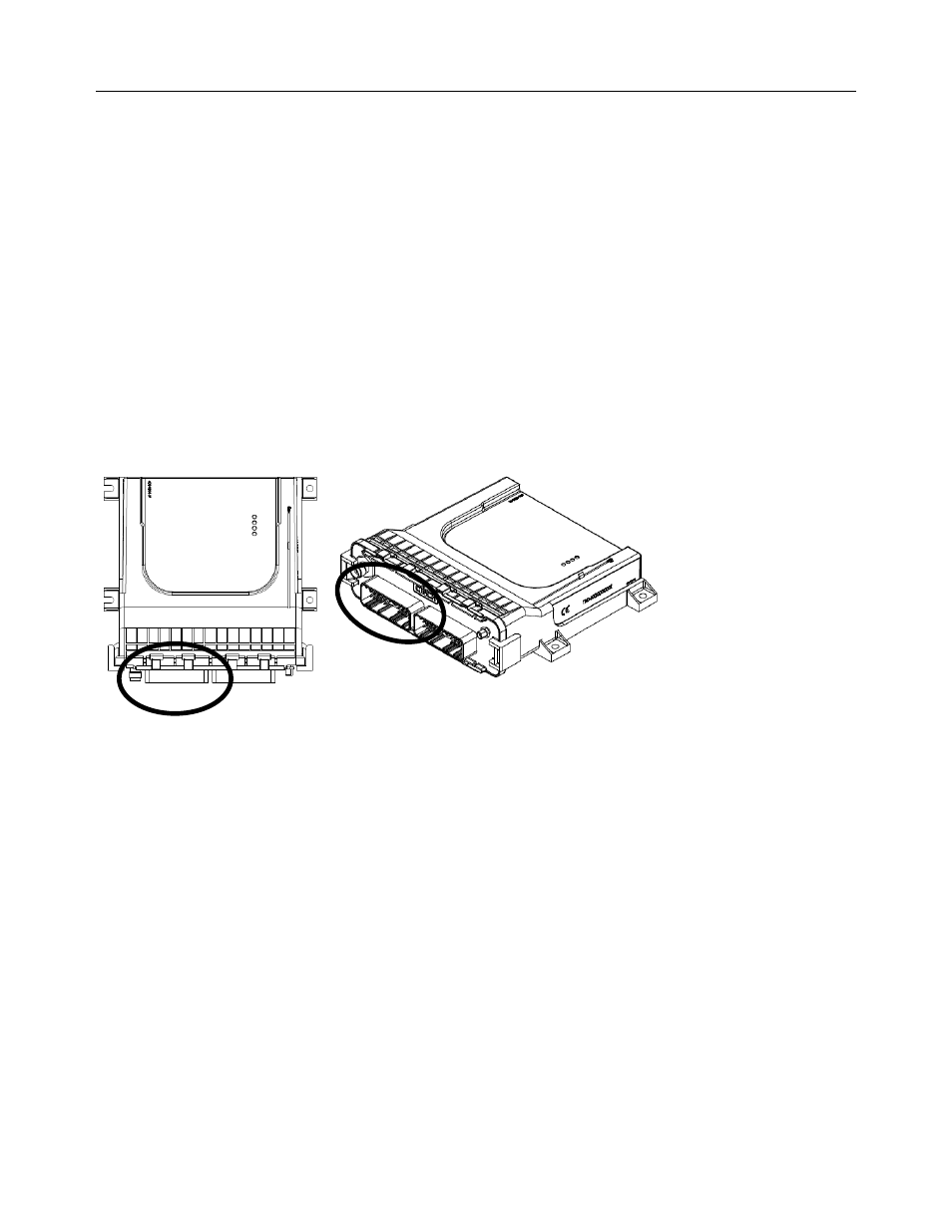
Attach Harnesses to GeoSteer Control Unit
Hardware
Installation
Guide
39
Depending on the installation, one or more of any of the following connections will need to be connected:
• Steering Valve
• Actuator
• Flow Sensor
• Mechanical Drive Unit
• Steering Wheel Encoder
• Wheel Angle Sensor
• Vehicle Interface Connections
• Pressure Transducers
Other connections not listed above could also be required but are explained in the vehicle-specific installation manuals.
GeoSteer Main Cable Harness
All GeoSteer systems are installed with a standard GeoSteer Main Cable Harness. This harness provides power and
communications to the Display and other accessories. This harness is connected to GeoSteer Control Unit’s left 30-pin port
with a 1/4" nut driver. The cable connector is keyed and has a Yellow dot that needs to be matched on the correct connector on
the GeoSteer Control Unit. Never force the connector.
Figure 8-13 Vehicle-Specific GeoSteer Control Unit Connector
Figure 8-14 shows the GeoSteer Main Cable Harness and the labels that are on each connector. Table 8-1 shows the functions
of each the GeoSteer Main Cable Harness cab connectors. Refer to the vehicle-specific instructions on how to connect the
EXPANSION and CAN connectors. Refer to your Display user manual for instructions on connecting the GeoSteer Main
Cable Harness connections shown to the correct ports and harnesses on the Display and Display harnesses for communications
and power.