John deere autotrac ready installation example – Ag Leader GeoSteer Installation Manual User Manual
Page 39
Cable Diagram Examples
Hardware
Installation
Guide
29
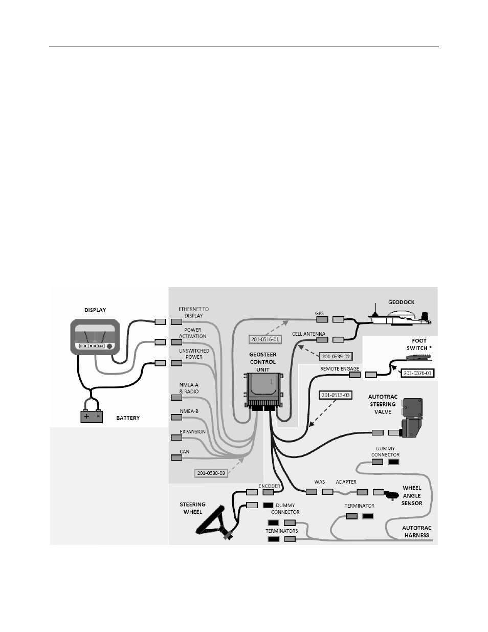
John Deere AutoTrac Ready Installation Example
• Cell Antenna Coax Cable (PN 201-0539-02) is not required if not using a Cell Modem.
• Foot Switch (PN 201-0376-01) is an optional accessory component.
• GeoSteer can be connected to multiple models of Displays. Refer to the Display User Manual for more detailed instructions
on how to connect the GeoSteer to the Display data and power ports.
• TERMINATORS are connected to the end of the vehicle’s AutoTrac Ready Harness at the two Steering Wheel Encoder
connectors and at the Wheel Angle Sensor connector. These parts are different depending on the model of the vehicle..
• DUMMY CONNECTORS are connected to the AutoTrac Steering Valve connector of the vehicle’s AutoTrac Ready
Harness and to the cable coming from the Steering Wheel Encoder that is not connected to the GeoSteer Harness.
• Wheel Angle Sensor ADAPTER Harness is installed to connect to the factory installed Wheel Angle Sensor to the
GeoSteer Harness. This adapter is different depending on the model of the vehicle..
• Component definitions
• DISPLAY – The Display that is connected to the GeoSteer system
• BATTERY – The battery terminals for the power source for the GeoSteer system and Display
• GEOSTEER CONTROL UNIT – The GeoSteer Control Unit
• GEODOCK – The GeoDock unit mounted on the roof
• FOOT SWITCH* – The optional Foot Switch that can be used for Remote Engage (not necessary for installation)
• STEERING WHEEL – This is the steering wheel which has an encoder attached to it for kick out
• AUTOTRAC STEERING VALVE – The factory supplied Steering Valve used to steer the vehicle
• WHEEL ANGLE SENSOR – The factory supplied Wheel Angle Sensor used to measure the angle of the wheel
position
• AUTOTRAC HARNESS – The existing factory supplied harness connecting the components
Figure 8-3 John Deere AutoTrac Ready Installation Example