Geosteer control unit installation – Ag Leader GeoSteer Installation Manual User Manual
Page 34
GeoSteer Control Unit Installation
24
GeoSteer System
GeoSteer Control Unit Installation
It is important that the GeoSteer Control Unit is mounted on a solid mounting bracket attached to a solid point on the vehicle.
The bracket must be sturdy enough to prevent any vibrations or move independently of the vehicle frame. The GeoSteer
Control Unit contains sensors that detect movement of the vehicle and any movement that is not directly related to the
vehicle’s frame may negatively affect control performance.
The GeoSteer Control Unit is weatherproof and can be mounted inside or outside the cab. However it is recommended in most
situations to mount the GeoSteer Control Unit inside the cab if possible. This is dependent on whether a solid location can be
located. The GeoSteer Control Unit can be mounted at any angle; however to simplify the vehicle setup steps in the AutoSteer
system later, it is recommended to install the GeoSteer Control Unit at right angles to the vehicle’s direction of motion. The
connectors should never point upwards.
The vehicle-specific installation kits provide the bracket, any additionally required hardware, and the instructions specific to
the vehicle that it is being installed on. The vehicle setup in the AutoSteer software also has the default angles for the GCU
loaded so odd angles can be used more easily. Refer to the ECU Bracket Installation Manual that comes with the installation
kit for instructions for installing the GeoSteer Control Unit.
Note: If the installation is a custom installation, it is important to mount the GeoSteer Control Unit at a solid point on the
vehicle. Failure to mount the GeoSteer Control Unit properly may cause the system to perform at a lower than optimum level.
Verify that the bracket is sturdy and that it can provide this solid mounting point.
Attach the GeoSteer Control Unit to the mounting bracket with four 8-32 x 1/2 Hex Screws or four 8-32 x 3/4" Hex Screws
(depending on the ECU Mounting Bracket) using a 1/4" nut driver. Do not over tighten.
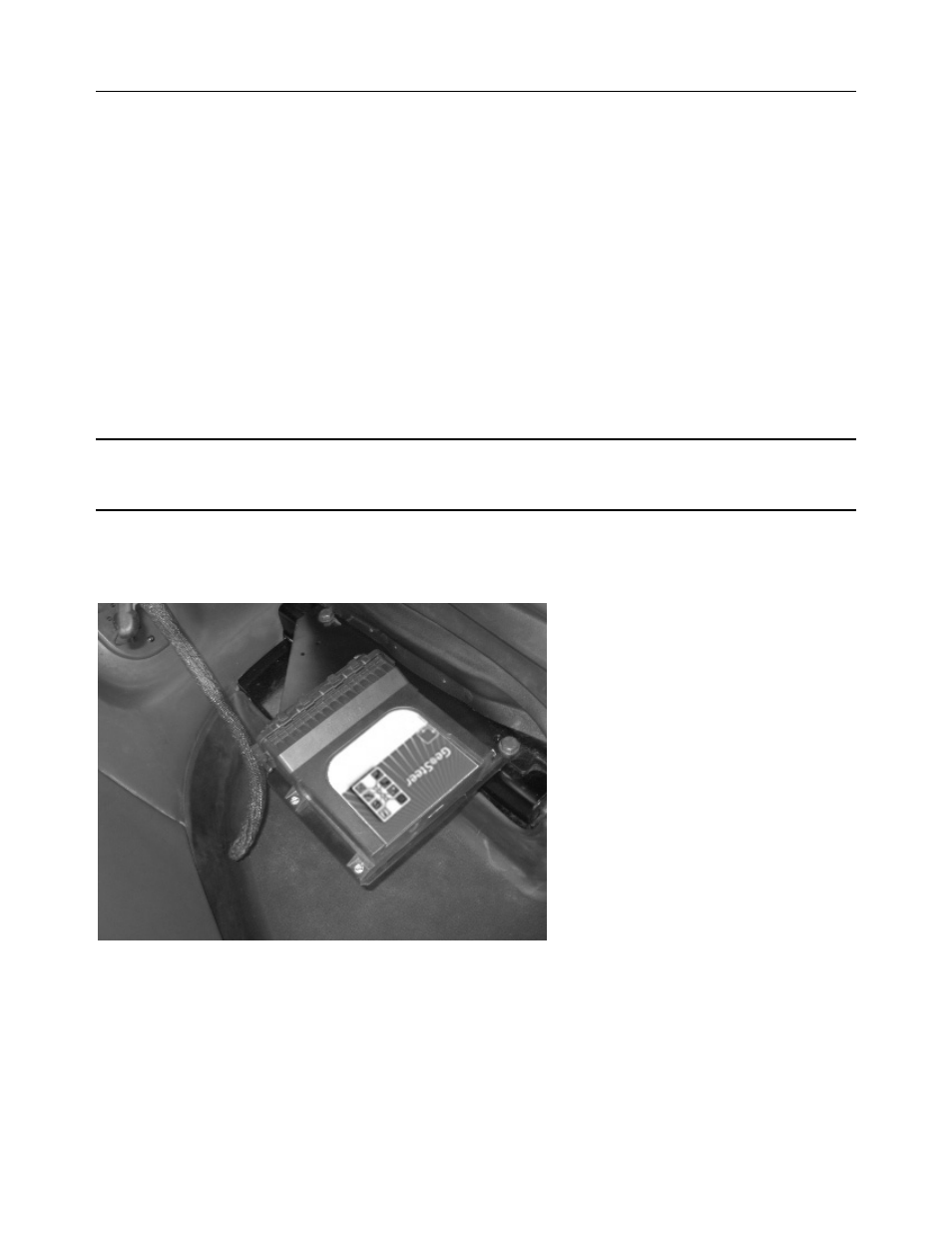
Figure 7-2 Example of GeoSteer Control Unit Installed
Refer to the GeoSteer Operator’s Manual for LED definitions and troubleshooting information based on the LED information.