Autosteer valve installation example – Ag Leader GeoSteer Installation Manual User Manual
Page 37
Cable Diagram Examples
Hardware
Installation
Guide
27
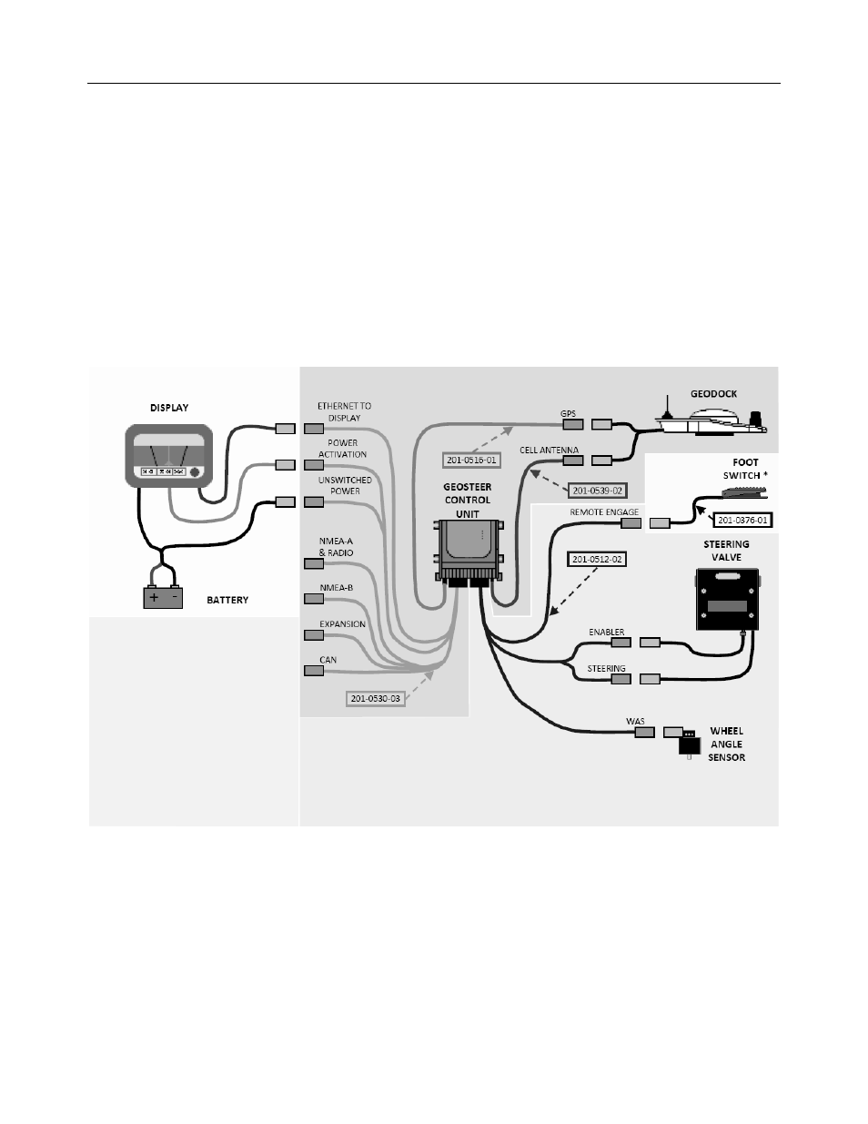
AutoSteer Valve Installation Example
• Cell Antenna Coax Cable (PN 201-0539-02) is not required if not using a Cell Modem.
• Foot Switch (PN 201-0376-01) is an optional accessory component.
• GeoSteer can be connected to multiple models of Displays. Refer to the Display User Manual for more detailed instructions
on how to connect the GeoSteer to the Display data and power ports.
• Component definitions
• DISPLAY – The Display that is connected to the GeoSteer system
• BATTERY – The battery terminals for the power source for the GeoSteer system and Display
• GEOSTEER CONTROL UNIT – The GeoSteer Control Unit
• GEODOCK – The GeoDock unit mounted on the roof
• FOOT SWITCH* – The optional Foot Switch that can be used for Remote Engage (not necessary for installation)
• STEERING VALVE – The Steering Valve used to steer the vehicle
• WHEEL ANGLE SENSOR – The device used to measure the angle of the wheel position
Figure 8-1 AutoSteer Valve Installation Example
- Yield Monitor 2000 Operators Manual (202 pages)
- Yield Monitor 2000 Quick Reference Sheets (2 pages)
- PF3000 Harvest & Application Operators Manual (259 pages)
- PF3000 Cotton Yield Monitor Operators Manual (149 pages)
- PF3000/PF3000Pro Harvest Master Mode Operators Manual (13 pages)
- PF3000/PF3000Pro Advanced Light Bar Operators Manual (59 pages)
- PF3000/PF3000Pro Harvest Mode Quick Reference Sheets (2 pages)
- PF3000/PF3000Pro Cotton Harvest Quick Reference Sheets (2 pages)
- PF3000/PF3000Pro Site Verification Mode Quick Reference Sheets (2 pages)
- PF3000/PF3000Pro Rawson Accu-Rate Direct Drive Quick Reference Sheets (9 pages)
- PF3000/PF3000Pro Rawson and New Leader Controllers Quick Reference Sheets (4 pages)
- PF3000/PF3000Pro Raven Controllers (with serial port) Quick Reference Sheets (4 pages)
- PF3000/PF3000Pro Raven Controllers (without serial port) Quick Reference Sheets (3 pages)
- PF3000/PF3000Pro Mid-Tech Controllers Quick Reference Sheets (4 pages)
- PF3000/PF3000Pro Dickey-john Land Manager Quick Reference Sheets (4 pages)
- PF3000/PF3000Pro Dickey-john Seed Manager Quick Reference Sheets (3 pages)
- PF3000/PF3000Pro Hiniker 8100 and 8150 Controllers Quick Reference Sheets (3 pages)
- PF3000/PF3000Pro Hiniker 8605 Controller Quick Reference Sheets (4 pages)
- PF3000/PF3000Pro TeeJet 844 Controller Quick Reference Sheets (4 pages)
- PF3000/PF3000Pro Flexicoil Flex Control Quick Reference Sheets (4 pages)
- PF3000/PF3000Pro Microtrack MT9000/Hardi 3500 Controllers Quick Reference Sheets (4 pages)
- PF3000/PF3000Pro Krohne Flow Meter Quick Reference Sheets (3 pages)
- PF3000/PF3000Pro Shaft Speed Sensor Quick Reference Sheets (3 pages)
- PF3000Pro Harvest & Application Operators Manual (294 pages)
- PF3000Pro Cotton Yield Monitor Operators Manual (168 pages)
- PFadvantage Harvest & Application Operators Manual (264 pages)
- PFadvantage Cotton Yield Monitor Operators Manual (166 pages)
- InSight Harvest Mode (4 pages)
- InSight Site Verification Mode (4 pages)
- InSight Tillage Mode (8 pages)
- InSight Flow Meter (9 pages)
- InSight Spinner Spreader (14 pages)
- InSight Strip-Till (10 pages)
- InSight NORAC UC5 (4 pages)
- InSight Direct Injection (4 pages)
- InSight Rawson and New Leader Controllers (5 pages)
- InSight Raven Serial, NL Mark V, SP6 (5 pages)
- InSight Mid-Tech Controllers (5 pages)
- InSight Direct Command Liquid (19 pages)
- Integra DirectCommand Clutch Control Quick Reference Guides (1 page)
- InSight SC Hydraulic Seed Rate Control (4 pages)
- InSight SC Stepper Seed Rate Control (3 pages)
- InSight SC KINZE PMM (3 pages)
- InSight SC Seed Tube Monitor (STMM) (16 pages)
- InSight Ver.8.0 Users Manual (342 pages)