Ag Leader Integra Users Manual User Manual
Page 324
308
Firmware Version 5.4
• Actuator Response 1
Determines the speed of the actuator when product
control error exceeds the Response Threshold setting.
Represents the fast speed of the actuator. Decreasing
the value will cause the actuator to run slower. The
default setting is 90%.
• Actuator Response 2
Determines the speed of the actuator when product
control error is less than the Response Threshold
setting. Represents the slow speed of the actuator.
Decreasing the value will cause the actuator to run
slower. The default setting is 18%.
• Response Threshold
Determines where the control channel switches between
using Actuator Response 1 and Actuator Response 2
speed settings. Leaving all other actuator control
settings at the default value and making a small
adjustment to this setting is usually all that is required to
fine-tune system performance. The default setting is 4.
- Decreasing this value will have the overall effect of
speeding up actuator response.
- Increasing this value will have the overall effect of
slowing actuator response.
• Allowable Error
Determines the percent of error that is allowed prior to
the product control system making any flow rate changes. 2% - 3% is the normal dead band setting range.
- Too low of a setting value can cause the product control system to continually hunt for the target
application rate.
- Too high of a setting will cause excessive product application error.
• Shaft Speed Cal
Calibration number representing the pulses that equal one revolution of the rate control metering system.
• Max Conveyor Speed
Setting determines the maximum RPM of the conveyor that controls product distribution to the application
point.
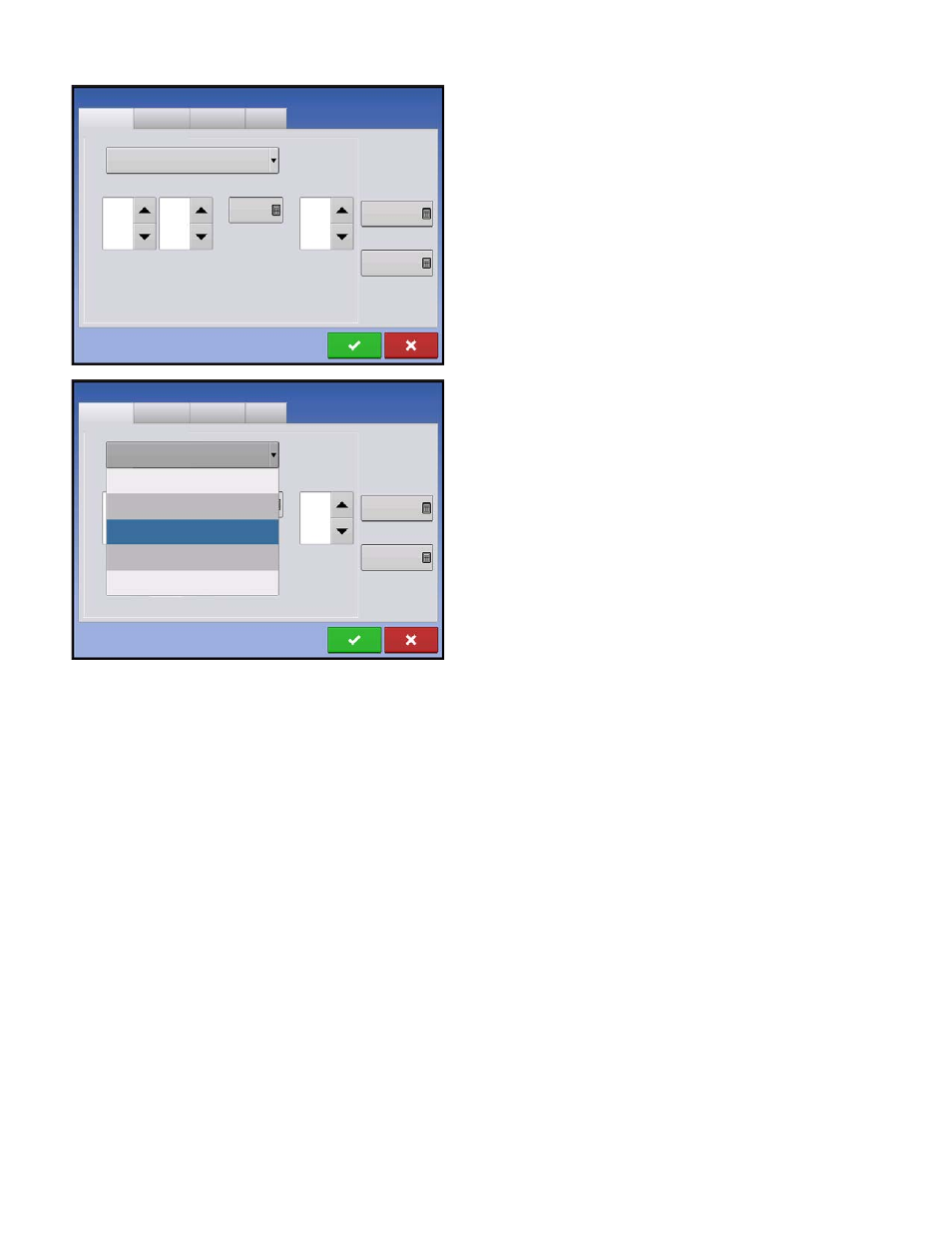
• Actuator/Clutch Configuration
Selecting one of the three available actuator/clutch settings: [Single Bin Actuator], [Multiple Bin Actuator,
Main Only], [Multiple Bin Actuator, Main + Channel] from the Control Valve Configuration drop-down menu
(above) determines specific behavior of the actuators/clutches on zero rate.
Strip Till Control
Channel 1
Channel 2
Channel 3
Auxiliary
Control Valve Configuration
Single Bin Actuator
Allowable
Error
2 %
Shaft Speed
Calibration
180 pls/rev
Max Metering
Speed
100 rpm
Actuator
Response 1
90 %
Actuator
Response 2
18 %
Response
Threshold
4
Channel 1
Channel 2
Channel 3
Control Valve Configuration
Auxiliary
Single Bin Actuator
Servo
PWM
Single Ben Actuator
Multiple Bin Actuator, Main Only
Multiple Bin Actuator, Main + Channel
Allowable
Error
2 %
Shaft Speed
Calibration
180 pls/rev
Max Metering
Speed
100 rpm
Strip Till Control