Table 3-14. revisions/test menu, 1 fixed gain using external reference control, Fixed gain using external reference control -37 – KEPCO BOP 1KW-MG Operator Manual, Firmware Ver.2.01 to 2.37 User Manual
Page 97: 14 revisions/test menu -37, R. 3.4.3.1, Le 3-14), R. 3.4.3.1 for
BOP HIPWR 022108
3-37
3.4.3.1
FIXED GAIN USING EXTERNAL REFERENCE CONTROL
The main channel of the BOP, voltage in voltage mode, and current in current mode, can be
controlled by an external reference voltage, 0 to ±10V applied at pin 11, referenced to pin 4, of
the Analog I/O port. The input impedance for this signal is 20K ohms. This feature is enabled as
follows:
1. From the power-up screen, press
$
, highlight Reference Input and press
!
. Highlight
External and press
$
to save. Then press
%
to apply the changes (without saving for
power-up) and exit. NOTE: This setting can be saved for power-up only by using the pass-
word-protected Power-up Settings menu (see {PAR. 3.3.7), otherwise internal references
are used for both main and protection channels upon power-up.
2. To return to digital or local control, from the power-up screen press
$
, then highlight Refer-
ence Input and press
!
. Highlight Internal and press
$
to save. Then press
%
to apply
the change and exit.
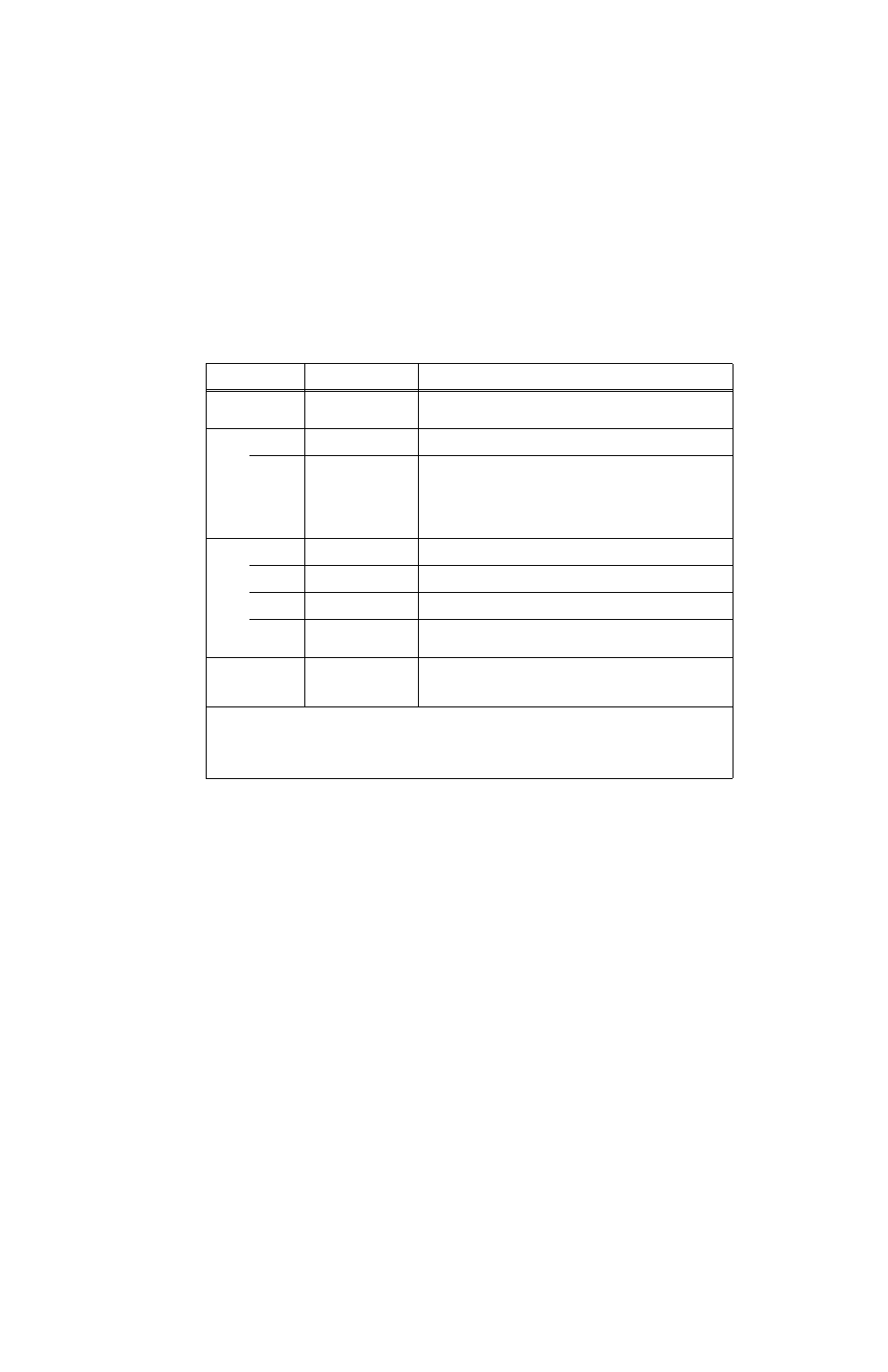
TABLE 3-14. REVISIONS/TEST MENU
SETTING
CHOICES
(BOLD = Factory Default)
FUNCTION
MAXIMUM OUTPUT
VOLTAGE XX
CURRENT YY
(Cannot be highlighted)
XX.0
YY.0
Displays rated output voltage and current of power supply. including all slaves
connected in parallel or series.
TEST
DISPLAY
Status (see NOTE below)
Automatic test, reports status messages (see NOTE below).
KEYPAD
Status (see NOTE below)
Requires depressing keys indicated on LCD.
This test requires pressing every key on the keypad, plus moving the
ADJUST control clockwise and counterclockwise, with the ADJUST control
depressed and released. As the keys and control function pass the tests, the
corresponding function on the LCD is highlighted. When the last test is suc-
cessful, the LCD displays “passed.” The test must be completed within two
minutes, otherwise a “Failed” indication is displayed.
INTER-
FACE
Status (see NOTE below)
Automatic test, reports status messages (see NOTE below).
SERIAL
Status (see NOTE below)
Automatic test of serial port - requires installation of loop back test connector.
(see PAR. 3.5.6.4). Reports status messages (see NOTE below).
ANALOG
Status (see NOTE below)
Automatic test which does not affect unit output. Reports status messages
(see NOTE below).
OUTPUT
Status (see NOTE below)
CAUTION: DISCONNECT LOAD BEFORE RUNNING THIS TEST. Output
is automatically programmed to +
E
Onom
for ~800 msec, then –
E
Onom
for
~800 msec, then to 0V. Reports status messages (see NOTE below).
REVISIONS
DISPLAY
INTERFACE
ANALOG
(Cannot be highlighted)
x.xx
y.yy
z.zz
Displays current firmware revision for display, interface and analog proces-
sors.
NOTE: Test status is as follows:
UNTESTED
Initial status when first entering menu.
TESTING
Test is running.
PASSED
Test was successful.
FAILED
Test failed.
FAIL EXT
SERIAL test failed - verify loop back connector installed (see PAR. 3.5.6.4).