Table 2-3. trigger port pin assignments, Caution, Trigger port pin assignments -3 – KEPCO BOP 1KW-MG Operator Manual, Firmware Ver.2.01 to 2.37 User Manual
Page 37: Able 2-4, Able 2-3, Able 2-2), Able 2-4.)
BOP HIPWR 022108
2-3
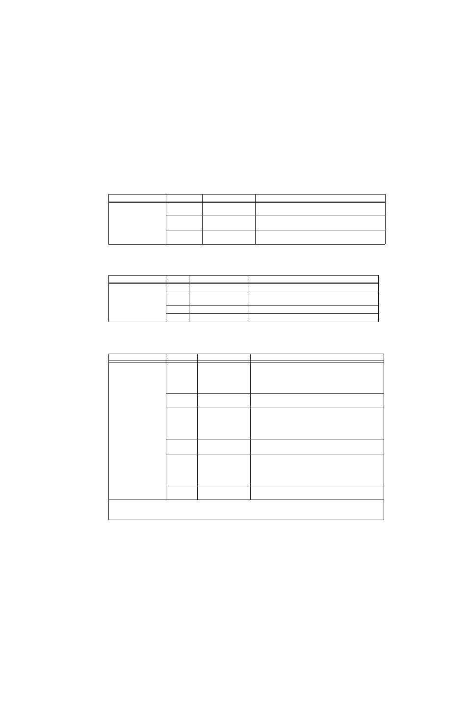
TABLE 2-2. IEEE 1118 CONNECTOR INPUT/OUTPUT PIN ASSIGNMENTS
CONNECTOR
PIN
SIGNAL NAME
FUNCTION
IEEE 1118 (BITBUS)
PORT
(connector A1J4)
1, 3 (shorted)
CONTROL BUS “A”
IEEE 1118, referenced to pins 5, 8
(2-Wire Differential Interface)
5, 8 (shorted)
CONTROL BUS “B”
IEEE 1118, referenced to pins 1, 3
(2-Wire Differential Interface)
6
TERMINATOR
Connect to pin 5 or 8 to add an internal termination resistor
to first/last unit on the daisy chain.
TABLE 2-3. TRIGGER PORT PIN ASSIGNMENTS
CONNECTOR
PIN
SIGNAL NAME
FUNCTION
TRIGGER PORT
(connector A1J3)
1
LOGIC GND
Return for TRIGGER and SHUTDOWN signals.
2
SHUTDOWN
Always active; Logic 0 causes unit to shut down (output
disabled, standby status);
3
NOT USED
4
EXT. TRIGGER INPUT
Not used; consult factory for details.
TABLE 2-4. EXTERNAL PROTECTION CONNECTOR INPUT/OUTPUT PIN ASSIGNMENTS
CONNECTOR
PIN
SIGNAL NAME
FUNCTION
EXT. PROTECT PORT
(connector A2A5J7)
1
SD_EXT_K
Cathode of LED optocoupler (through a 510 ohm resistor)
which is used for external isolated shutdown. Anode of LED
is connected to (A2A5J7) pin 2. A positive voltage (3.5 to
15V) at pin 2 (referenced to pin 1) shuts down the unit (see
CAUTION below).
2
SD_EXT_A
Anode of LED optocoupler which is used for external iso-
lated shutdown. (See pin 1 above.)
3
PG_EXT_C
Collector of optocoupler-transistor which is used for external
isolated “power OK” flag. Transistor emitter is connected to
(A2A5J7) pin 4. When unit is operating normally, transistor is
saturated. Current through transistor should not exceed 5mA
and supply voltage should not exceed 15V.
4
PG_EXT_E
Emitter of optocoupler-transistor which is used for external
isolated “power OK” flag. (See pin 3 above.)
5
EXT_C
Collector of optocoupler-transistor which is used for external
isolated “Output OFF” flag. Transistor emitter is connected to
(A2A5J7) pin 6. When output is OFF, transistor is saturated.
Current through transistor should not exceed 3mA and sup-
ply voltage should not exceed 15V.
6
EXT_E
Emitter of optocoupler-transistor which is used for external
isolated “output OFF” flag. (See pin 5 above.)
CAUTION:When an external shut-down signal is sent to the unit, the shut-down condition is latched and the red FAULT
indicator on the front panel is ON. To resume normal operation it is necessary to cycle power off, then on (preferred) or
briefly press the RESET key on the front panel.