8 storing/recalling power supply output settings, Storing/recalling power supply output settings -21, Ble 3-7 illus – KEPCO BOP 1KW-MG Operator Manual, Firmware Ver.2.01 to 2.37 User Manual
Page 81: 7 ill
BOP HIPWR 022108
3-21
word is required, see PAR. 3.2.4.4 for instructions.) Highlight the parameter and press
!
to
modify. Use
Y
,
U
or the
ADJUST
control to highlight a selection, then press
$
to save. To
change a value use the number keys to enter new setting, then
$
to save. When all power-up
settings have been configured, press
$
to save for power up or
%
to exit and abort the
change.
To restore the factory default power-up settings listed above, from the power-up screen press
%
. Highlight Power-up Settings and press
!
. Then press
@
to restore the defaults. Then
press
$
to save for power up or
%
to exit and abort the change.
These settings can be directly applied to a load upon power-up. Many other configurable set-
tings can be saved for power up using the
$
key after modifying the setting
3.3.8
STORING/RECALLING POWER SUPPLY OUTPUT SETTINGS
The power supply settings (mode, main channel reference type and setting, protection limit type
and setting and output status) can be stored in one of 99 memory locations for later recall. This
feature is accessible from the front panel by pressing
!
from the power-up screen to view the
Saved Settings screen (Figure 3-8). For a description of abbreviations used, refer to PAR.
3.3.8.1 To view previously saved settings refer to PAR 3.3.8.2. To save the power supply set-
tings or modify previously saved settings refer to PAR. 3.3.8.3. To recall saved settings and
apply them to the output refer to PAR. 3.3.8.5.
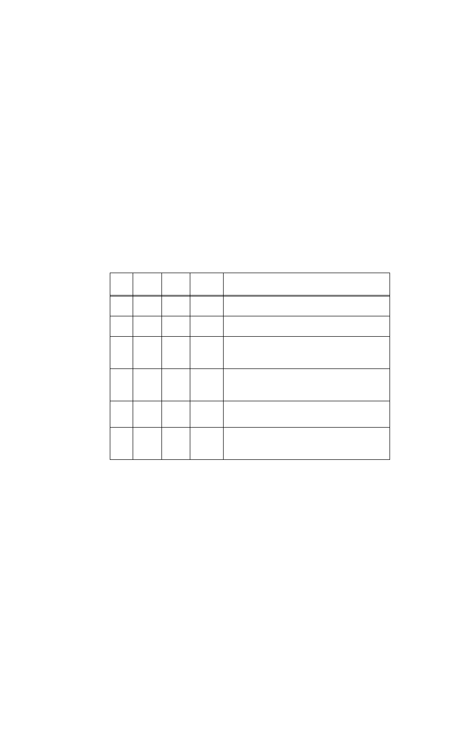
TABLE 3-7. EXAMPLES SHOWING HOW POWER-UP SETTINGS FUNCTION
Mode
Main
Channel
Protection
Type
Levels
Power-up condition (output ON)
(All referenced pins located on Analog I/O Port
see PAR. 3.4 and Figure 2-1)
Voltage
Internal
Internal
Voltage: 10
Current: 25
Unit powers up in voltage mode, 0V, ±current protection set to 25A. Pressing
MODE changes mode to current, puts unit in standby: output to 0A, ±voltage
protection to power-up setting of 10V, output off and STANDBY indicator on.
Current
Internal
Internal
Voltage: 10
Current: 25
Unit powers up in current mode, 0A, ±voltage protection set to 10V. Pressing
MODE changes mode to voltage, puts unit in standby: output to 0V, current
protection to power-up setting of 25A, output off and STANDBY indicator on.
Voltage
External
or
ExtRefLvl
Internal
Voltage: 10
Current: 25
Unit powers up in voltage mode, output voltage determined by Analog port,
pin 11 (see PAR. 3.4.3.1 for External, PAR. 3.4.3.2 for ExtRefLvl), ±current
protection set to 25A. Pressing MODE changes mode to current, puts unit in
standby, ±voltage protection to power-up setting of 10V. When output is on
(STANDBY indicator off), output current determined by pin 11.
Current
External
or
ExtRefLvl
Internal
Voltage: 10
Current: 25
Unit powers up in current mode, output current determined by Analog port,
pin 11 (see PAR. 3.4.3.1 for External, PAR. 3.4.3.2 for ExtRefLvl), ±voltage
protection set to 10V. Pressing MODE changes mode to voltage and puts unit
in standby, ±current protection to power-up setting of 25A. When output is on
(STANDBY indicator off), output voltage determined by pin 11.
Voltage
Internal
External
or Lesser
Limit
Voltage: 10
Current: 25
Unit powers up in voltage mode, 0V, ±current protection determined by pins 5
and 13 (see PAR. 3.4.4 for External, PAR. 3.4.4.1 for Lesser Limit). Pressing
MODE changes mode to current, puts unit in standby. When output is on,
(STANDBY indicator off), ±voltage protection determined by, pins 6 and 14.
Current
Internal
External
or Lesser
Limit
Voltage: 10
Current: 25
Unit powers up in Current mode, 0A, ±voltage protection determined by pins
6 and 14 (see PAR. 3.4.4 for External, PAR. 3.4.4.1 for Lesser Limit). Press-
ing MODE changes mode to voltage, puts unit in standby. When output is on,
(STANDBY indicator off), output voltage is 0V, ±current protection deter-
mined by, pins 5 and 13.