2 viewing saved settings, Table 3-8. save/recall menu, Viewing saved settings -23 – KEPCO BOP 1KW-MG Operator Manual, Firmware Ver.2.01 to 2.37 User Manual
Page 83: Save/recall menu -23, R 3.3.8.2. t, R. 3.3.8.3, 8 ar
BOP HIPWR 022108
3-23
3.3.8.2
VIEWING SAVED SETTINGS
1. Pressing
!
from the power-up screen displays the Saved Setups screen (Figure 3-8) con-
sisting of a list of locations 1 through 20 arranged in two columns of 10 rows. Use
T
and
R
keys to display additional columns. NOTE: Use the number keys as a shortcut, e.g., press-
ing
4
immediately highlights location 41, showing the column with locations 41 through 50.
2. Use the
U
and
Y
keys to highlight the desired memory location; When the desired location
is highlighted, press
!
. The details of the parameters listed in Table 3-8 are displayed.
3.3.8.3
SAVING SETTINGS AND ERASING OR MODIFYING PREVIOUSLY SAVED SETTINGS
1. Press
!
from the power-up screen to enter the Saved Setups screen (Figure 3-8).
2. Use the
U
and
Y
keys to highlight the desired memory location; To erase a highlighted
memory location, press
#
. The list will show erased locations as
Empty
.
3. Press
!
to see the details stored in the highlighted location.
4. Once the details are displayed, use the
U
and
Y
keys to highlight the desired parameter.
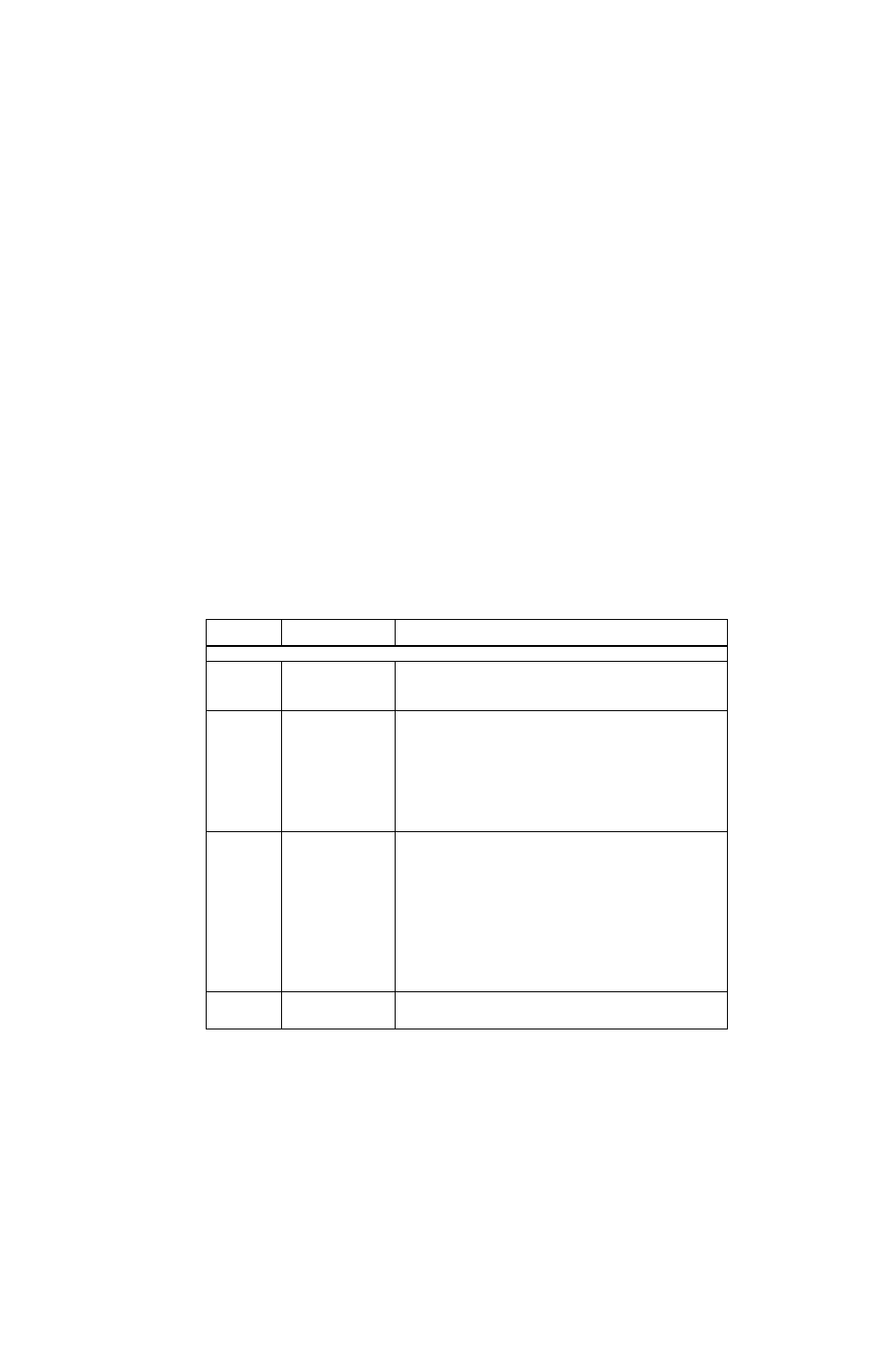
TABLE 3-8. SAVE/RECALL MENU
PARAMETER
CHOICES
(BOLD = Factory Default)
FUNCTION
NOTE: DEFAULT values for empty cells are the settings of the unit at the time the save/recall menu is entered.
MODE
VOLT
CURRENT
EXTERNAL
VOLT - Selects voltage mode. Voltage value determined by SETTING.
CURRENT - Selects current mode. Current value determined by SETTING.
EXTERNAL - Used for customized configuration where EXT VM/CM signal at pin
2 of I/O port controls mode; consult factory for details.
MAIN CHANNEL
REFERENCE
INTERNAL
EXTERNAL
EXTL REF LVL
INTERNAL: Any external reference applied to the Analog I/O port pin 11 is ignored
and the internal reference established by SETTING field.
EXTERNAL: The internal reference is ignored, and the external reference applied
to the Analog I/O port pin 11 is used (see PAR. 3.4.3.1).
EXTL REF LVL: Allows the gain of the BOP to be established by the maximum
output voltage or current introduced by the SETTING field. (see PAR. 3.4.3.2).
SETTING
nn.nnn or
nnn.nnn
(model and parameter
dependent)
Sets the active channel setting. E.g., if VOLT mode is selected, nnn.nnn is voltage
setting, if CURRENT mode is selected, nn.nnn is current setting. If EXTERNAL
mode is selected, SETTING is not available.
PROTECTION
MODE
INTERNAL
EXTERNAL
LESSER LIMIT
INTERNAL - Allows limits to be controlled by POSITIVE and NEGATIVE values.
EXTERNAL: Allows limits to be controlled by analog signals applied to the analog
port (see PAR. 3.4.4).
LESSER LIMIT: Allows protect limit to be automatically selected from either 1) the
external analog voltage applied to the Analog I/O port or 2) the value set in the
POSITIVE and NEGATIVE fields. Whichever limit has a lower absolute value
(closest to zero) has effect (see PAR. 3.4.4).
POSITIVE nn.nnn
or
nnn.nnn
This is the positive value for Voltage protect if CURRENT mode is selected, or the
positive value for Current protect if VOLTAGE mode is selected. If EXTERNAL
mode is selected, this field is not accessible.
NEGATIVE
nn.nnn or
nnn.nnn
This is the negative value for Voltage protect if CURRENT mode is selected, or the
negative value for Current protect if VOLTAGE mode is selected. If EXTERNAL
mode is selected, this field is not accessible.
OUTPUT
OFF
ON
OFF - Output disabled. The behavior of the unit when output is disabled depends
on the LOAD TYPE setting (see PAR.3.3.6).
ON - Output enabled.