Figure 4-1. calibration setup, Calibration setup -6 – KEPCO BOP 1KW-MG Operator Manual, Firmware Ver.2.01 to 2.37 User Manual
Page 130
4-6
BOP-1K 022108
2. For FULL SCALE calibration adjust the output to obtain the closest value above
the nominal full scale value.
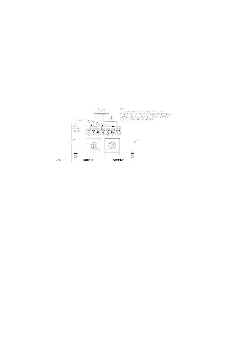
3. Set the unit for local sensing with GND Network in (see Figure 4-1) and discon-
nect load from BOP output to prepare the unit for voltage calibration.
FIGURE 4-1. CALIBRATION SETUP
1. Initiate calibration by sending the SCPI command
SYSTem:PASSword:CENable DEFAULT
and then send
CAL:STATe 1
. The password
DEFAULT
has been set at the factory. If the
password has been changed from
DEFAULT
, substitute the correct password for the unit in
the
SYST:PASS:CEN
command. If the password has been lost, consult factory.
2. Set the BOP to zero volts output by sending
CAL:VOLT ZERO
. Connect a Digital Voltmeter
(DVM) to the BOP OUT S and COM S terminals to measure the output voltage. Send
CAL:DATA
commands as needed (see PAR. 4.3c) to adjust the BOP output until the DVM
reads as close to zero as possible within tolerance specified in Table 4-3 for VOLTAGE
ZERO.
3. Set the BOP to maximum positive output voltage by sending
CAL:VOLT MAX
. Measure the
voltage output using the DVM. To adjust, send
CAL:DATA
commands as needed (see PAR.
4.3b) until the DVM reading is as close as possible above the nominal full scale value within
the tolerance specified in Table 4-3 for +FULL SCALE VOLTAGE.
4. Set the BOP to maximum negative output voltage by sending
CAL:VOLT MIN
. To adjust,
send the
CAL:DATA
command as needed (see PAR. 4.3b)
until the reading is as close as
possible above (absolute value) the nominal full scale value within the limits specified in
Table 4-3 for –FULL SCALE VOLTAGE.
5. Send
CAL:VPR MAX
to adjust the maximum positive voltage protection limit of the power
supply. Send the
CAL:DATA
commands as needed (see PAR. 4.3c)
until the reading is as
close as possible above the nominal full scale value within the limits specified in Table 4-3 for
+FULL SCALE VPR LIMIT.
6. Send
CAL:VPR MIN
to adjust the maximum negative protection limit of the power supply.
Send the
CAL:DATA
commands as needed (see PAR. 4.3c)
until the reading is as close as
possible above (absolute value) the nominal full scale value within the limits specified in
Table 4-3 for –FULL SCALE VPR LIMIT.