Current shunt (sense resistor) connections -8, 15 cali – KEPCO BOP 1KW-MG Operator Manual, Firmware Ver.2.01 to 2.37 User Manual
Page 132
4-8
BOP-1K 022108
NOTE: Accuracy of the 10V d-c reference must be ±0.1mV in order for the calibrated unit to
meet published specifications.
15.Connect a –10V ±0.1mV d-c reference to pin 8 (S_IN_SERIAL) of the PAR/SER CONTROL
IN connector (A2A5J3) referenced to COM S terminal at the rear panel. Set the BOP to max-
imum positive output voltage by sending
CAL:SER MAX
. Measure the voltage output using
the DVM. Send
CAL:DATA
commands as needed (see PAR. 4.3a) until the DVM reading is
as close as possible to +10V.
16.Send
CAL:ZERO
to prepare for current calibration. After sending the command, the BOP out-
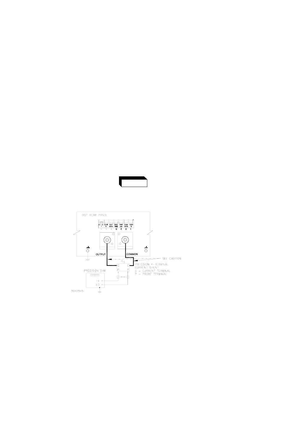
put will be set to zero volts. Refer to Figure 4-2 to connect the C terminals of the Kelvin type
sense resistor to the BOP and connect the DVM to the P (probe) terminals of the sense
resistor ((LO terminal of DVM to common P terminal). Table 4-4 provides recommended
sense resistor values for various BOP current outputs, as well as the formula for calculating
expected measured values and tolerances for any sense resistor other than those recom-
mended. Table 4-2 lists Kepco and Manufacturer part numbers for those sense resistors rec-
ommended.
The sense resistor will be dissipating full rated current of the BOP. If
it is hot to the touch, the sense resistor value, power rating and/or
cooling are incorrect; refer to PAR. 4.3 and Table 4-2.
FIGURE 4-2. CURRENT SHUNT (SENSE RESISTOR) CONNECTIONS
17.Set the BOP to zero volts across the sense resistor (corresponding to zero current) by send-
ing
CAL:CURR ZERO
. Send
CAL:DATA
commands as needed (see PAR. 4.3a)
until the
reading is as close to zero as possible within the limits specified in Table 4-4 for CURRENT
ZERO.
WARNING
CAUTION
WIRES BETWEEN BOP OUTPUT AND
SENSE RESISTOR MUST BE RATED TO
CARRY THE RATED OUTPUT
CURRENT OF THE POWER SUPPLY.
AWG#6 IS RECOMMENDED.