Operation via hart, 1 conditions of communication line, Operation via hart -1 – Yokogawa RotaMASS 3-Series User Manual
Page 65: 1 conditions of communication line -1, L = 65x10, Rxc) (c
6. OpErATION vIA HArT
6-1
IM 01R04B04-00E-E 8th edition March 01, 2011 -00
All Rights Reserved. Copyright © 2003, Rota Yokogawa
6. OpErATION vIA HArT
6.1 Conditions of communication line
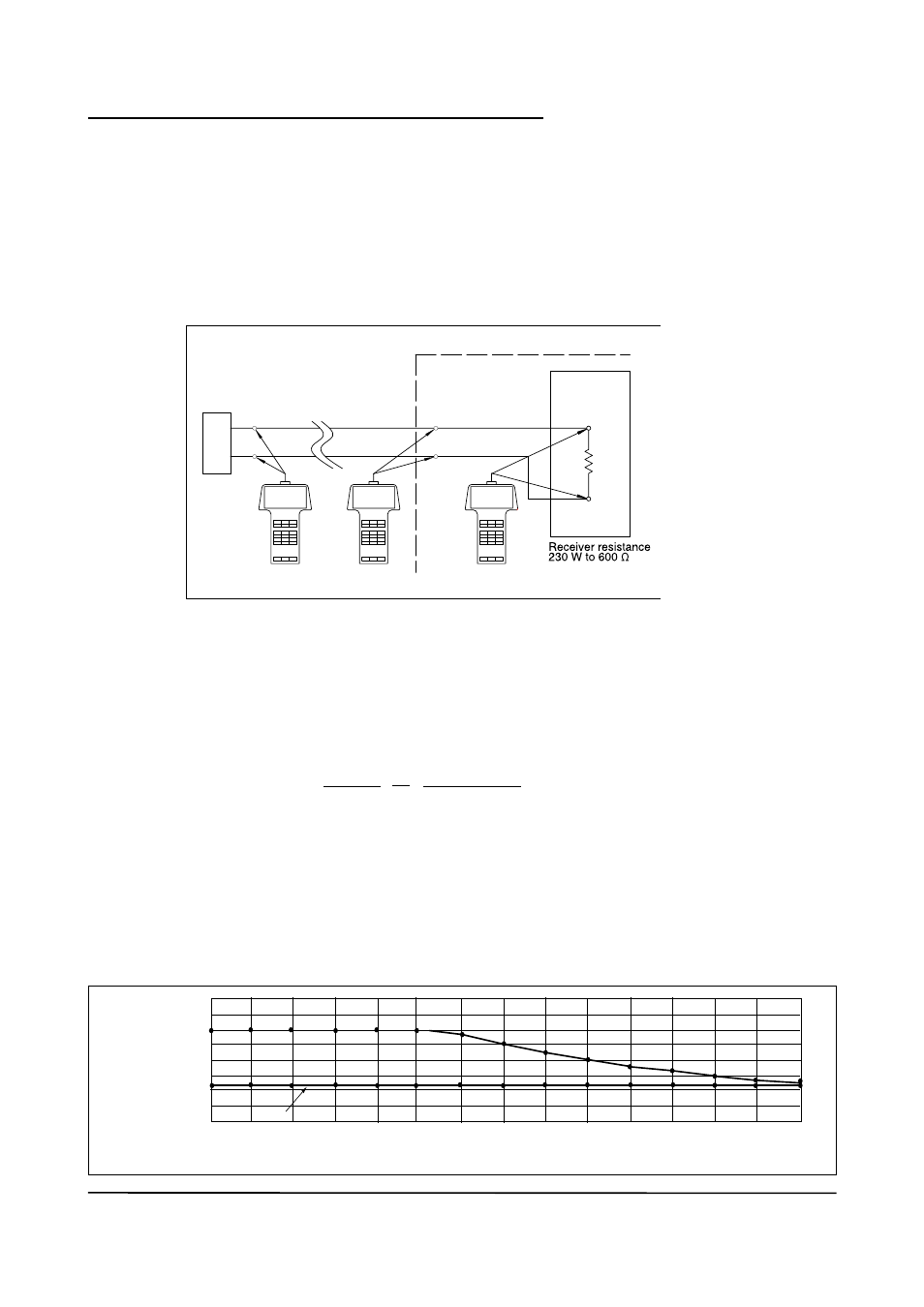
A HART-communicator can communicate with the ROTAMASS RCCT_F3 from the control room, the
ROTAMASS site or any other wiring termination point in the loop, provided there is a minimum load
resistance of 230Ω between the connection and the instrument. To communicate, it must be connected in
parallel with the ROTAMASS RCCT_F3, the connections are not polarized. The figure below shows the wiring
connections for direct interface at the ROTAMASS RCCT_F3.
Specifications of communication line :
Load resistance
:
230 to 600 Ω, for multidrop mode see figure below
Minimum cable size
:
24 AWG (0.51 mm diameter)
Cable type
:
single pair shielded or multiple pair with overall shield
Maximum twisted pair length
:
6,500 ft (2,000 m)
Maximum multiple twisted pair length :
3,200 ft (1,000 m)
Use the following formula to determine cable length for a specific application :
Where :
L = length in feet or meters
R = resistance in ohms, current sense resistance
C = cable capacitance in pF/ft or pF/m
C
i
= 50,000 pF
Load resistance and quantity of devices in multidrop mode :
800
700
600
500
400
300
200
100
0
1
2
3
4
5
6
7
8
9
10
11
12
13
14
15
Load
resistance
[ Ω ]
Quantity of connected field devices
F62.EPS
230
571
500
333
307
285 266
400
444
363
RCCT_F3
HART
Communicator
HART
Communicator
HART
Communicator
Intermediate
terminals
4 to 20mA DC
signal trans-
mission line
Receiving
instrument
Terminal board
Control room
F61.EPS
L =
65x10
6
(RxC)
(C
f
+10,000)
C