Remote field-mount type rccf31 with rccs3 – Yokogawa RotaMASS 3-Series User Manual
Page 197
9. EXplOSION prOTECTEd TYpE INSTrUMENTS
9-5
All Rights Reserved. Copyright © 2003, Rota Yokogawa
IM 01R04B04-00E-E 8th edition March 01, 2011 -00
remote field-mount type rCCF31 with rCCS3
WARNING
1.
Ex-type RCCF31 and RCCS3 must be connected to the suitable IS earthing system
(see installation diagram). Converter and detector case must have connection to the potential
equalisation facility.
2.
Use the certified cable glands, suitable for the conditions of use.
3.
Please confirm that the ground terminal (inside the terminal enclosure) is firmly
connected by means of a clip-on eye-let.
4.
Ex-e terminals for power supply and I/O-lines are designed for cables with cross section of 0.08 mm²
(AWG 28) to 2.5 mm² (AWG 22). The strip length must be 5 to 6 mm (0.2 to 0.24 in).
5.
For EMC technical reasons the case of the detector is connected to the case of the
converter via the shielding of the interconnecting cable.
Cable glands for power- and I/O-cables :
RCCF31-xxxM : Ex e types are enclosed. These cable glands can also be used for “dust application” (D).
Use ATEX-certified Ex d cable glands for Ex d condition.
RCCF31-xxxA
: No cable glands are enclosed. Use the ATEX-certified cable glands, suitable for the
conditions of use (Ex de or Ex d or dust application)
For “dust application” (D) use cable glands with minimum IP67 protection !
Cable glands for detector connection terminal :
RCCF31-xxxM : Cable glands are fitted in the concerning thread. This cable gland can be used for
“dust application” (D).
RCCF31-xxxA : Cable glands are enclosed. This cable gland can also be used for “dust application” (D).
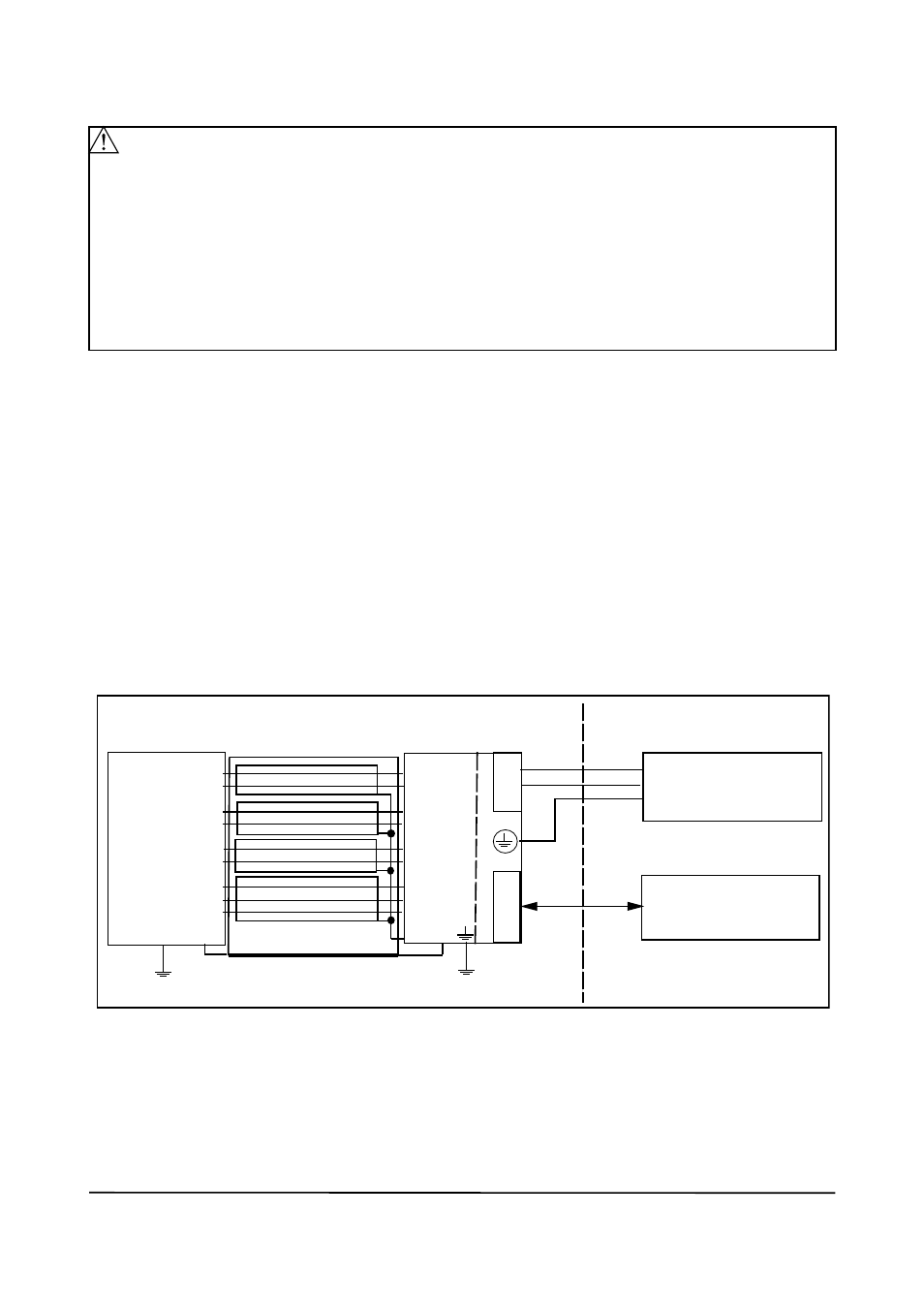
Installation diagram (option /KF1) :
L/+
N/-
G
Power supply
I/O control
Hazardous area
Safe area
I/O
RCCF31
RCCS3
D+
D-
S1+
S1-
S2+
S2-
TP1
TP2
TP3
D+
D-
S1+
S1-
S2+
S2-
TP1
TP2
TP3
COM
Exclusive remote cable RCCY03
F92.EPS
Terminal Box
The inner shields (shields of the cable pairs) are connected together to COM – terminal on converter side.
The outer shield of the cable is connected on both sides to the cases by cable gland.
Detailed information for connection intrinsic safe outputs (option /KF2) see chapter 4.8.8