2 data flow diagram, Data flow diagram -3, 1) ejxmvtool – Yokogawa EJX930A User Manual
Page 76: Operation of flownavigator program, Figure 6.2 data flow diagram of ejxmvtool
<6. Operation of FlowNavigator Program>
6-3
IM 01C25R51-01E
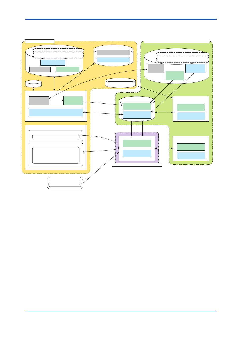
6.1.2 Data Flow Diagram
(1) EJXMVTool
EJXMVTool
XMV File
User Flow
Parameters
Device Flow
Parameters
Device General
Parameters
Compatible between different frame application
Compatible between HART and
F
OUNDATION
fieldbus DTMs
Report File(csv)
User Flow Parameters
Device General Parameters
EJX910 HART/F
OUNDATION
fieldbus DTM
DNS/DFS File
Not compatible between different frame application
Not compatible between HART and
F
OUNDATION
fieldbus DTMs
Device General
Parameters
Device Flow
Parameters
User Flow
Parameters
PRM File
(Note3)
Device General
Parameters (HART)
Import
Offline Parameter
Device Flow Parameters
Device Flow Parameters
Device
General Parameters
Offline Database
Device
General Parameters
Device Flow
Parameters
Online Parameter
Device
General Parameters
Device Flow Parameters
(Not displayed)
(Not displayed)
EJX Multivariable Transmitter
Device General
Parameters
Device Flow
Parameters
(Note1)
Sensor Input
F0602E.ai
DP, SP, ET
DP, SP, ET
(Auto Compensation/Basic Mode)
User Flow
Parameters
(Note2)
Device General Parameters
Flow Configuration Wizard
Obtain Flow Coefficient
Simulated Sensor Input
Flow Calculation Output
Process Value (DP,SP,ET)
Flow Coefficient (Flow, Density,
Viscosity,Gas Expansion Factor,
Discharge Coefficient, Reynolds No.)
Auto
Compensation
Mode
initialize
Apply
Start up /
Apply
Simulated Input
*
Read Parameter *
Input*
Read/
Write*
Enter
Start up/
Open/
Save
As
Open/
Save
As
Save As
Open
/
Export
Import/
Export
to Device*
Device
*
Downloa
d
Lead from
*: Online function (executed while connect)
Note1) Device does not hold User Flow Parameter.
Note2) User Flow Parameters consist of fluid
information and operating condition.
Note3) Generated by FSA210.
Can be imported to HART DTM.
Figure 6.2
Data flow diagram of EJXMVTool