Retransmit and alarm output, Outputs 1a and 1b, Continued) – Watlow Series F4P User Manual
Page 89: Mechanical relay, Retransmit outputs x (1 and 2), Alarm outputs x (1 and 2), Figure 8.11a, Figure 8.11b, Figure 8.11c
Wa t l o w S e r i e s F 4 P
I n s t a l l a t i o n a n d W i r i n g
■
8 . 1 1
Outputs 1A and 1B
(continued)
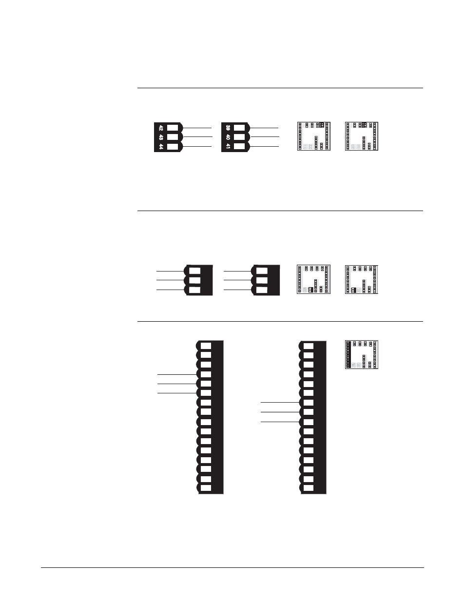
Figure 8.11a —
Mechanical Relay
Retransmit and Alarm Output
Figure 8.11b —
Retransmit Outputs x (1 and 2)
mA maximum load impedance is 800
Ω
VÎ (dc) minimum load impedance is 1K
Ω
Figure 8.11c —
Alarm Outputs x (1 and 2)
Electromechanical relay without contact suppression
Form C, 2 amp, off-state impedance is 31m
Ω
1
2
3
4
5
6
7
8
9
1
0
1
1
1
2
1
3
1
4
1
5
1
6
1 2
3 4
5 6
7 8
9 1
0 11 12 13 14
15 16
1
7
1
8
1
9
2
0
2
1
2
2
2
3
2
4
2
5
2
6
2
7
2
8
2
9
3
0
3
1
3
2
17 18 19 20
21 22 23 24
25 26
27 28 29 3
0 31 32
59 60 61 6259 60 61 62
48 49 5048 49 50
45 46 4
7
45 46 47
51 52 53 54
55 5
6 57 5
8
51 52 53 54 55 56 57 5
8
3
3
3
4
3
5
33 34 35
3
6
3
7
3
8
36 37 38
3
9
4
0
4
1
39 40
41
4
2
4
3
4
4
42 43 44
4
5
1
2
3
4 5
6
7
8
9
10
11 12 13 1
4
15 16
1 2 3
4 5
6 7
8
9 10
11 12 13 14 15 16
COM.
N.O.
6
N.C.
7
8
1
2 3
4
5
6 7
8
9 10 1
1 1
2 13
14 15 16
1 2 3
4 5
6 7 8
9 10 1
1 12 13 14
15 16
COM.
N.O.
9
N.C.
Alarm Output 1
Alarm Output 2
volts 48
Output 1
1
2
3
4
5
6
7
8
9
1
0
1
1
12
1
3
1
4
15
1
6
1
2
3
4 5 6
7 8
9 1
0
11
12
1
3
1
4 15
1
6
1
7
1
8
1
9
2
0
2
1
2
2
2
3
2
4
2
5
2
6
2
7
28
2
9
3
0
3
1
3
2
1
7
1
8 1
9
20 2
1
22
23
2
4 25
26
27
28 29
30
3
1
32
59
6
0
61
62
59
60
61
62
48 4
9 50
48 4
9 50
45
4
6 4
7
45
46 47
5
1 52
53
54
55
5
6 57
58
5
1 52
53
54 55
56
57
58
3
3
3
4
3
5
33
3
4 35
3
6
3
7
3
8
36
37
3
8
3
9
4
0
4
1
39 40
41
4
2
4
3
4
4
4
2
43
44
1
2
3
4
5
6
7
8
9
1
0
1
1
1
2
1
3
1
4
1
5
1
6
1
2
3
4
5
6
7
8 9
1
0
11 1
2
1
3
1
4 1
5
1
6
1
7
1
8
1
9
2
0
2
1
2
2
2
3
2
4
2
5
2
6
2
7
2
8
2
9
3
0
3
1
3
2
1
7
1
8 1
9
20
2
1
22
23
2
4 25
26 27 2
8 29
30
3
1
32
59
60
61
62
59
60
61
62
48 4
9 50
48 4
9 50
45 4
6 4
7
45 46 47
51
5
2
53 54
55
56 57
58
51
52
53
54 55
56
57
58
3
3
3
4
3
5
33
3
4 35
3
6
3
7
3
8
36 37
3
8
3
9
4
0
4
1
39
40
41
4
2
4
3
4
4
4
2 43
44
Output 2
F4P_ - _ _ _ _ - 1 _ _ _
or F4P_ - _ _ _ _ - 2 _ _ _
F4P_ - _ _ _ _ - 2 _ _ _
COM. 49
amps 50
48 49 5048 49 50
45 46 4745 46 47
volts 45
COM. 46
amps 47
39 N.O.
40 COM.
41 N.C.
42 N.O.
43 COM.
44 N.C.
F4P_ -E _ _ _-_ _ _ _
F4P_ -_E_ _ - _ _ _ _
Output 1A
Output 1B
✔ Note: Switching
inductive loads (relay
coils, solenoids, etc.)
with the mechanical
relay, switched dc or
solid-state relay output
options requires use of
an R.C. suppressor.
Watlow carries the R.C.
suppressor Quencharc
brand name, which is a
trademark of ITW
Paktron. Watlow Part No.
0804-0147-0000.
ç
WARNING: To avoid
damage to property and
equipment, and/or injury
or loss of life, use
National Electric Code
(NEC) standard wiring
practices to install and
operate the Series F4P.
Failure to do so could
result in such damage,
and/or injury or death.
ç
CAUTION: Maintain
isolation between outputs
1A, 1B and between the
retransmit outputs to
prevent ground loops. A
ground loop may cause
incorrect readings or
error codes. Failure to
follow this guideline
could result in damage to
equipment and product.