Slidewire control – Watlow Series F4P User Manual
Page 76
7 . 1 8
■
F e a t u r e s
Wa t l o w S e r i e s F 4 P
Slidewire Control
The Series F4P with the enhanced control option can be
configured to support slidewire valve control. In
slidewire control a closed-loop process value, is measured
at analog input 1 and compared to the control set point.
The difference between the measured value and the con-
trol set point generates an error signal which is acted on
by PID to generate a percent output. The percent output
generated by PID is compared to the slidewire resistance
measured at analog input 3 to determine if the valve
needs to be closed or opened to decrease the difference
between the closed loop process value and set point.
Two, time-proportioned outputs are required to control
the valve position. Control output 1A is used to close the
valve and output 1B is used to open the valve. Output 1A
can be configured as heat (reverse) acting or cool (direct)
acting. With output 1A set to cool (direct) the valve will
open as the process value increases and power in the
manual mode will be adjustable from 0% to 100%. With
output 1A set to heat (reverse) the valve will close as the
process value increases and power in the manual mode
will be adjustable from 0% to +100%.
With PID generating a 25% output, output 1A set to cool
(direct), a slide-wire resistance range of 100 to 1200
ohms and slidewire resistance measured on analog input
3 is greater than 275 ohms (25% of span) output 1B will
be on opening the valve to increase the cooling effect to
decrease the process value until the measured resistance
equals 25% of span. With the same conditions and the
measured resistance less than 275 ohms (25% of span)
output 1A will be closing the valve to decrease the cool-
ing effect until the measured resistance equals 25% of
span.
To select slideware control, set Analog Input 3 > Sensor
to Slidewire. The slidewire feature can be calibrated ei-
ther automatically or manually.
Fine tune the behavior of the slidewire control using the
Hunt and Hysteresis parameters, in Setup Page > Ana-
log Input 3 > Slidewire.
Location in software: Setup Page > Analog Input 3.
Figure 7.18a — Slidewire Hunt and Hysteresis.
Slidewire Position
Set Point
Turn-on Point (open)
Turn-on Point (close)
Temperature
Turn-off Point (close)
Turn-off Point (open)
Slidewire
Hysteresis
Hunt
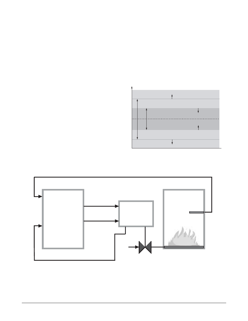
Figure 7.18b — Slidewire Feedback Application Example.
Input 1 -
Sensor
Output 1A = Close
Input 3 -
Set Point
F4P
Enhanced
Temperature
Sensor
Gas Furnace
Valve Actuator
Output 1B = Open
Gas Flow
Slidewire Input