Wiring the series f4p, Input-to-output isolation, Power wiring – Watlow Series F4P User Manual
Page 83: Sensor installation guidelines
Wa t l o w S e r i e s F 4 P
I n s t a l l a t i o n a n d W i r i n g
■
8 . 5
Wiring the Series F4P
Wiring options depend on the model number, which is
printed on the label on the back of the controller. The
model number codes are explained in the Appendix.
The labels on the sides and back of the controller contain
some basic wiring information.
Input-to-Output Isolation
The Series F4P uses optical and transformer isolation to
provide a barrier to prevent ground loops when using
grounded sensors and/or peripheral equipment.
Here is a breakdown of the isolation barriers:
• Analog input 1 and all the digital inputs are grouped
together.
• Analog inputs 2 and 3 are grouped together.
• All the control outputs and retransmit outputs are
grouped together.
• Both alarm outputs are grouped together.
• Communications is isolated from the other inputs
and outputs.
Figure 8.5a — Isolation Blocks.
ç
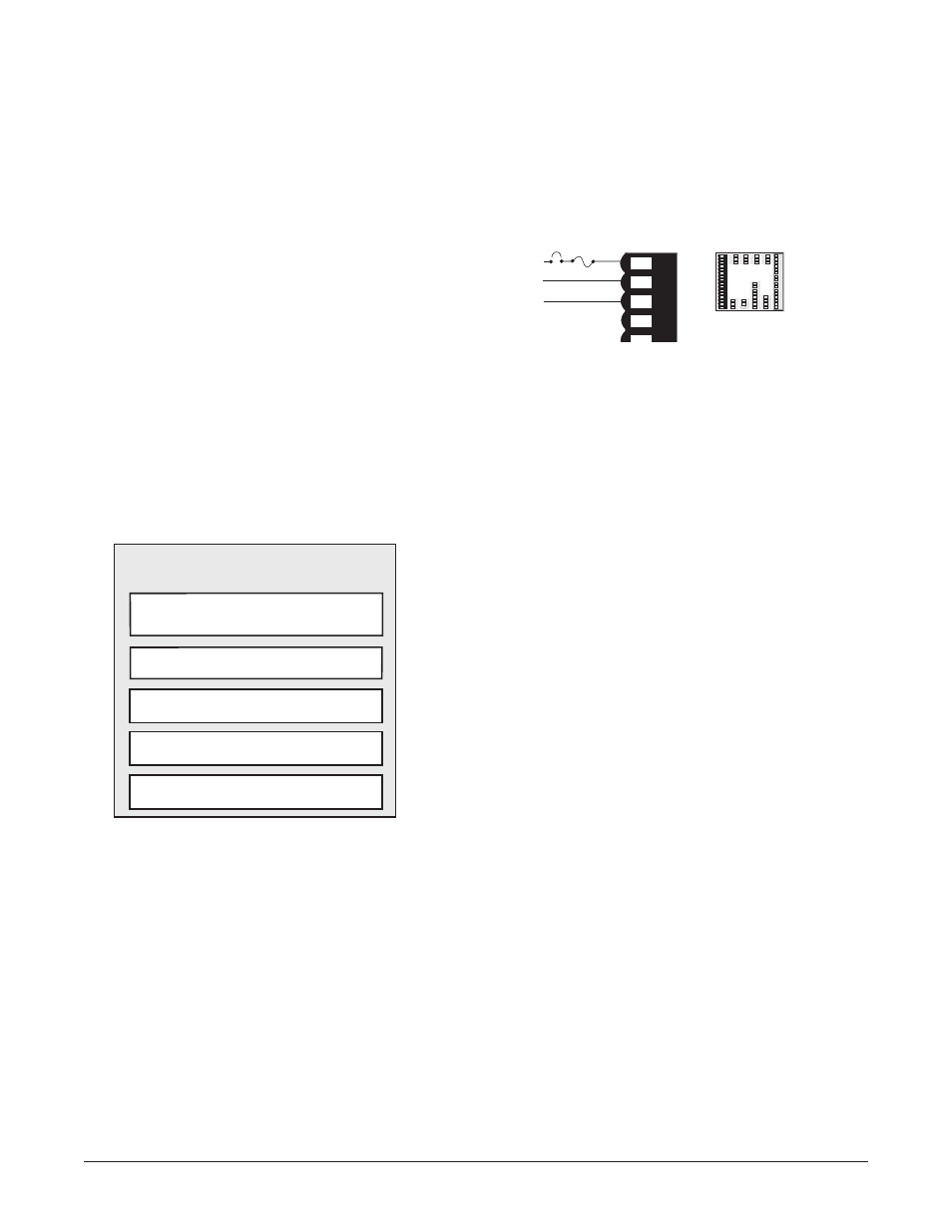
WARNING: Provide a labeled switch or circuit breaker
connected to the Series F4P power wiring as the means of
disconnection for servicing. Failure to do so could result
in damage to equipment and/or property, and/or injury or
death to personnel.
Power Wiring
100 to 240V‡ (ac/dc), nominal (85 to 264 actual) F4PH - _
_ _ _ - _ _ _ _
The Series F4P has a non-operator-replaceable fuse Type
T (time-lag) rated at 2.0 or 5.0A @ 250VÅ (ac).
Figure 8.5b — Power Wiring.
Sensor Installation Guidelines
Thermocouple inputs: Extension wire for
thermocouples must be of the same alloy as the
thermocouple to limit errors.
If a grounded thermocouple is required for input 2, the
signal to input 3 must be isolated to prevent possible
ground loops.
RTD input: Each 1 of lead wire resistance can cause a
+2°F error when using a two-wire RTD. A three-wire
RTD sensor overcomes this problem. All three wires must
have the same electrical resistance (i.e., same gauge,
same length, multi-stranded or solid, same metal).
Process input: Isolation must be maintained between
input 2 and input 3. If both input 2 and input 3 are
process signals, a separate power supply and transmitter
must be used for each input. These inputs must be
electrically isolated from one another to prevent ground
loops.
∫
WARNING: To avoid damage to property and equipment,
and/or injury of loss of life, use National Electric Code
(NEC) standard wiring practices to install and operate the
Series F4P. Failure to do so could result in such damage,
and/or injury or death.
1
2
3
4
5
6
7
8
9
1
0
1
1
1
2
1
3
1
4
1
5
1
6
1 2 3 4 5 6 7 8 9 10 11 12 13 14 15 16
1
7
1
8
1
9
2
0
2
1
2
2
2
3
2
4
2
5
2
6
2
7
2
8
2
9
3
0
3
1
3
2
17 18 19 20 21 22 23 24 25 26 27 28 29 30 31 32
5
9
6
0
6
1
6
2
59 60 61 62
4
8
4
9
5
0
48 49 50
4
5
4
6
4
7
45 46 47
5
1
5
2
5
3
5
4
5
5
5
6
5
7
5
8
51 52 53 54 55 56 57 58
3
3
3
4
3
5
33 34 35
3
6
3
7
3
8
36 37 38
3
9
4
0
4
1
39 40 41
4
2
4
3
4
4
42 43 44
1
2
1
2
3
4
5
1 2 3 4 5 6 7 8 9 10 11 12 13 14 15 16
L2
3
Earth Ground
+
-
fuse
ÅL1
Isolation Blocks
There are no electrical connections between these blocks.
Analog Input 1
Digital Inputs
Analog Input 2 and 3
Control Outputs
Retransmit Outputs
Alarm Outputs
Communications