Inputs x (2 and 3) (continued), 0 to 50mv, Slidewire input (input 3 only) – Watlow Series F4P User Manual
Page 86: Figure 8.8a, Figure 8.8b, Figure 8.8c, Figure 8.8d
8 . 8
■
I n s t a l l a t i o n a n d W i r i n g
Wa t l o w S e r i e s F 4 P
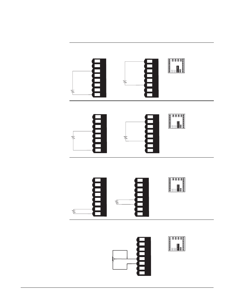
Inputs x (2 and 3) (continued)
Figure 8.8a —
0-5VÎ, 1-5VÎ or 0-10VÎ (dc) Process
F4P _ - _ _ AB - _ _ _ _
Input impedance: 20k
Ω
Figure 8.8b —
0-20mA or 4-20mA Process
F4P _ - _ _ AB - _ _ _ _
Input impedance: 100
Ω
Figure 8.8c —
0 to 50mV
F4P _ - _ _ AB - _ _ _ _
Impedance: 20M
Ω
Figure 8.8d —
Slidewire Input (Input 3 only)
F4P _ - _ _ _AB - _ _ _ _
Slidewire resistance range: 100 to 1200
Ω
51 52 53 54 55 56 57 58 51 52 53 54 55 56 57 58
CW
CCW
Wiper
55
56
Input 3
1
2
3
4
5
6
7
8
9
1
0
1
1
1
2
1
3
1
4
1
5
1
6
1 2 3
4 5
6 7 8 9 10 11 12
13 14
15 16
1
7
1
8
1
9
2
0
2
1
2
2
2
3
2
4
2
5
2
6
2
7
2
8
2
9
3
0
3
1
3
2
17 18 19
20 21 2
2 23 24
25 26
27 28 29
30 31 3
2
5
9 60 61 62
59 60 61 62
4
8 49 50
48 49 50
45 46 4
7
45 46 47
51
52
5
3 54
55 56 57 58
51 52 53 54
55 56 57 58
3
3
3
4
3
5
33 34 35
3
6
3
7
3
8
36 37 38
3
9
4
0
4
1
39 40 41
4
2
4
3
4
4
42 43 44
+57
-58
51 52 53 54 55 56 57 58 51 52 53 54 55 56 57 58
+55
-56
51 52 53 54 55 56 57 58 51 52 53 54 55 56 57 58
Input 2
Input 3
1
2
3
4
5
6
7
8
9
1
0
1
1
1
2
1
3
1
4
1
5
1
6
1 2
3 4
5
6
7
8
9
10
11 12
13 14 15 16
1
7
1
8
1
9
2
0
2
1
2
2
2
3
2
4
2
5
2
6
2
7
2
8
2
9
3
0
3
1
3
2
1
7
1
8
19
20
21 22 23 24 2
5
26 2
7
28
29 30
31 32
59 6
0
61 62
59 60
61 62
48 4
9
5
0
48 49
5
0
45 4
6 4
7
45 46 47
51 52 53
54
55
5
6
57
58
51
52 53 54 55
5
6 57
5
8
3
3
3
4
3
5
33 34 35
3
6
3
7
3
8
36 3
7
38
3
9
4
0
4
1
3
9
40
41
4
2
4
3
4
4
42 43 44
51 52 53 54 55 56 57 58 51 52 53 54 55 56 57 58
+54
-58
51 52 53 54 55 56 57 58 51 52 53 54 55 56 57 58
+52
-56
Input 2
Input 3
1
2
3
4
5
6
7
8
9
1
0
1
1
1
2
1
3
1
4
1
5
1
6
1 2 3 4 5 6 7
8 9 1
0 11 12
13 14 15 16
1
7
1
8
19
2
0
2
1
2
2
2
3
2
4
2
5
2
6
2
7
2
8
2
9
3
0
3
1
3
2
17 18 1
9
20
21 22 23 24 25 26 27 28 29 30
31 32
59
60 61 62
59
60 61 62
4
8 4
9
5
0
48 49
50
45 46 4745 46 47
5
1 52 53 5
4 55 56 57
5
8
51 52 53 54 55 56 57
58
3
3
3
4
3
5
33 34
35
3
6
3
7
3
8
36 37 38
3
9
4
0
4
1
3
9 40
41
4
2
4
3
4
4
42 43
44
51 52 53 54 55 56 57 58 51 52 53 54 55 56 57 58
+53
-58
51 52 53 54 55 56 57 58 51 52 53 54 55 56 57 58
+51
-56
Input 2
Input 3
1
2
3
4
5
6
7
8
9
1
0
1
1
1
2
1
3
1
4
1
5
1
6
1 2 3 4 5
6 7
8
9
1
0 11 12
13 14 15 16
1
7
1
8
19
2
0
2
1
2
2
2
3
2
4
2
5
2
6
2
7
2
8
2
9
3
0
3
1
3
2
17 18
1
9 20
21 22 23 24 25 26 27 28 29
30
31 32
59 6
0
61 62
59 60
61 62
48 4
9
5
0
48 4
9
50
4
5 4
6 47
45 46 47
51 52 53 54
5
5 56 57
58
51 52 53 54 55 56 57 58
3
3
3
4
3
5
33 34 35
3
6
3
7
3
8
36 37 38
3
9
4
0
4
1
3
9
40
41
4
2
4
3
4
4
42 43
44
ç
WARNING: To avoid
damage to property and
equipment, and/or injury
or loss of life, use
National Electric Code
(NEC) standard wiring
practices to install and
operate the Series F4P.
Failure to do so could
result in such damage,
and/or injury or death.
ç
CAUTION: Maintain
isolation between analog
inputs 2 and 3, and
between analog input 1
and digital inputs 1- 4 to
prevent a ground loop. A
ground loop may cause
incorrect readings or
error codes. Failure to
follow this guideline
could result in damage to
equipment and product.
ç
WARNING: Process
inputs may not have
sensor break protection.
Outputs can remain full
on.