Inputs x (2 and 3), Thermocouple, Figure 8.7a – Watlow Series F4P User Manual
Page 85: Figure 8.7b, Figure 8.7c
Wa t l o w S e r i e s F 4 P
I n s t a l l a t i o n a n d W i r i n g
■
8 . 7
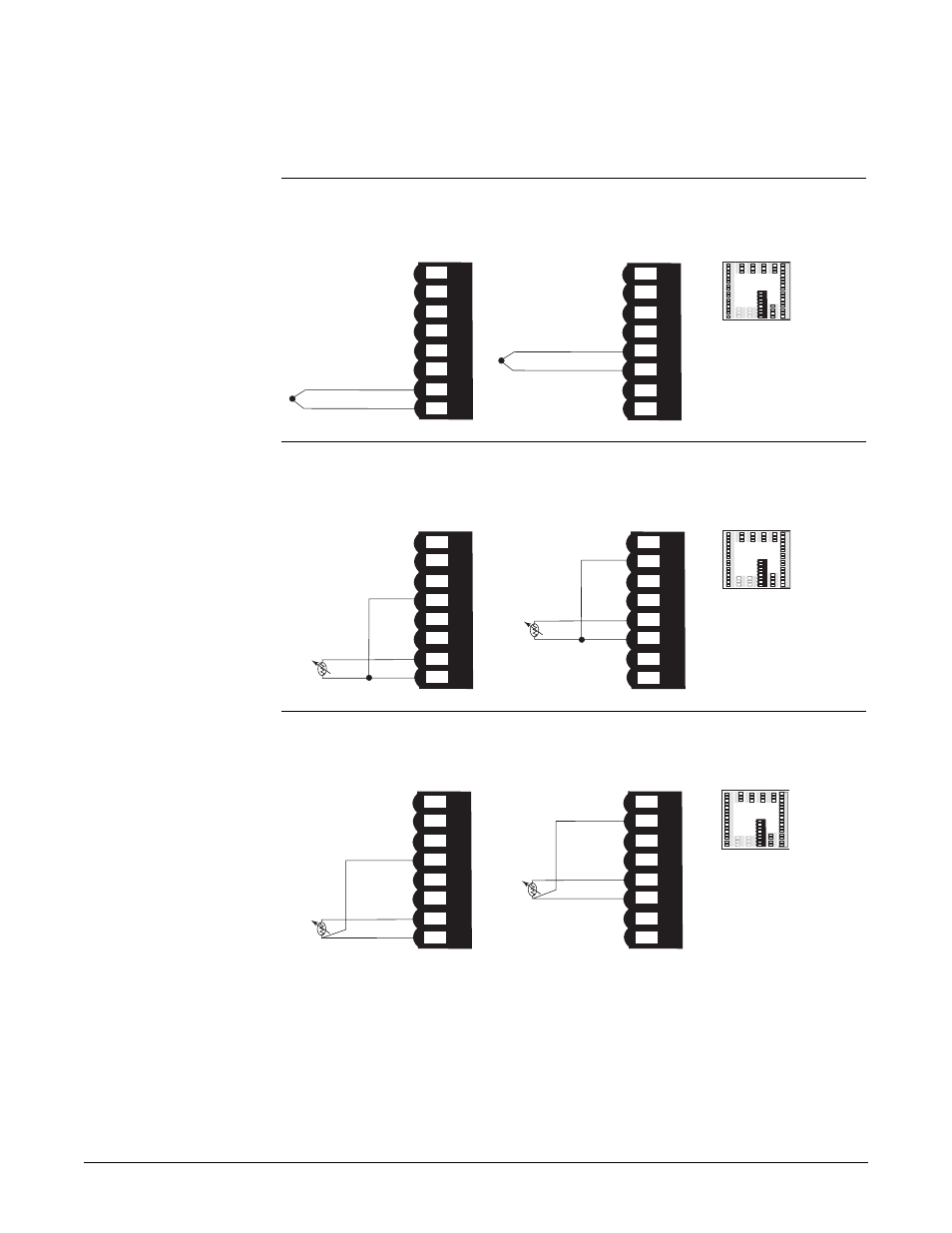
Inputs x (2 and 3)
Figure 8.7a
—
Thermocouple
F4P _ - _ _ AB - _ _ _ _
Impedance: 20M
Ω
Figure 8.7b —
RTD (2-wire) 100, 500 or 1000
Ω
Platinum
F4P _ - _ _ AB - _ _ _ _
The last two digits of the model number determine RTD calibration.
Figure 8.7c —
RTD (3-wire) 100, 500 or 1000
Ω
Platinum
F4P _ - _ _ AB - _ _ _ _
The last two digits of the model number determine RTD calibration.
51 52 53 54 55 56 57 58 51 52 53 54 55 56 57 58
54
57
58
S1
S3
S2
51 52 53 54 55 56 57 58 51 52 53 54 55 56 57 58
52
55
56
S1
S3
S2
Input 2
Input 3
1
2
3
4
5
6
7
8
9
1
0
1
1
1
2
1
3
1
4
1
5
1
6
1 2
3 4
5 6 7
8 9
10
11 12
13 14 15 16
1
7
1
8
19
2
0
2
1
2
2
2
3
2
4
2
5
2
6
2
7
2
8
2
9
3
0
3
1
3
2
17 18 1
9
20
21 22 23 24 25 26 27 28 29
30
31 32
5
9 6
0 61 6
2
5
9 60 61 62
48 4
9
5
0
48 4
9
50
45 46 4
7
45 46 47
5
1 52 53 5
4 55 56 57
58
51 52 53 54 55 56 57
58
3
3
3
4
3
5
33 34 35
3
6
3
7
3
8
36 37
38
39
4
0
4
1
39
40
41
4
2
4
3
4
4
42 43 44
51 52 53 54 55 56 57 58 51 52 53 54 55 56 57 58
54
57
58
S1
S3
jumper 54 to 58
51 52 53 54 55 56 57 58 51 52 53 54 55 56 57 58
52
55
56
S1
S3
jumper 52 to 56
Input 2
Input 3
1
2
3
4
5
6
7
8
9
1
0
1
1
1
2
1
3
1
4
1
5
1
6
1 2 3 4
5 6 7
8
9 1
0
11 12
13 14 15 16
1
7
1
8
1
9
2
0
2
1
2
2
2
3
2
4
2
5
2
6
2
7
2
8
2
9
3
0
3
1
3
2
17 18
1
9
20 21 22 23 24 25 26 27 28
2
9
30
31 32
5
9 6
0 61 62
5
9 60 61 62
48 4
9 5
0
48 4
9 50
45 46 4745 46 47
5
1 52 53 5
4 55 56 5
7
58
51 52 53 54 55 56 57
58
3
3
3
4
3
5
33 34 35
3
6
3
7
3
8
36 37
38
3
9
4
0
4
1
3
9
40
41
4
2
4
3
4
4
42 43
44
+57
-58
51 52 53 54 55 56 57 58 51 52 53 54 55 56 57 58
+55
-56
51 52 53 54 55 56 57 58 51 52 53 54 55 56 57 58
Input 2
Input 3
1
2
3
4
5
6
7
8
9
1
0
1
1
1
2
1
3
1
4
1
5
1
6
1 2
3 4
5
6
7
8
9
10
11 12
13 14 15
16
17
1
8
1
9
2
0
2
1
2
2
2
3
2
4
2
5
2
6
2
7
2
8
2
9
3
0
3
1
3
2
17
1
8
19
20
21 22 23 24 2
5
26 2
7
28
29 30
31 32
59 6
0
61 62
59 60
61 62
48 4
9
5
0
48 49
5
0
45 46 4
7
45 46 47
5
1
52
53
54
55
5
6
57
58
5
1
52 53 54 55
5
6 57 58
3
3
3
4
3
5
33 34 35
3
6
3
7
3
8
36 3
7
38
3
9
4
0
4
1
3
9
40
41
4
2
4
3
4
4
42 43 44
ç
WARNING: To avoid
damage to property and
equipment, and/or injury
or loss of life, use
National Electric Code
(NEC) standard wiring
practices to install and
operate the Series F4P.
Failure to do so could
result in such damage,
and/or injury or death.
ç
CAUTION: Maintain
isolation between analog
inputs 2 and 3, and
between analog input 1
and digital inputs 1- 4 to
prevent a ground loop. A
ground loop may cause
incorrect readings or
error codes. Failure to
follow this guideline
could result in damage to
equipment and product.