2 setting parameters required for operation – IAI America PCON-PO User Manual
Page 54
42
4. Operation Using I/O Signals
4.2.2
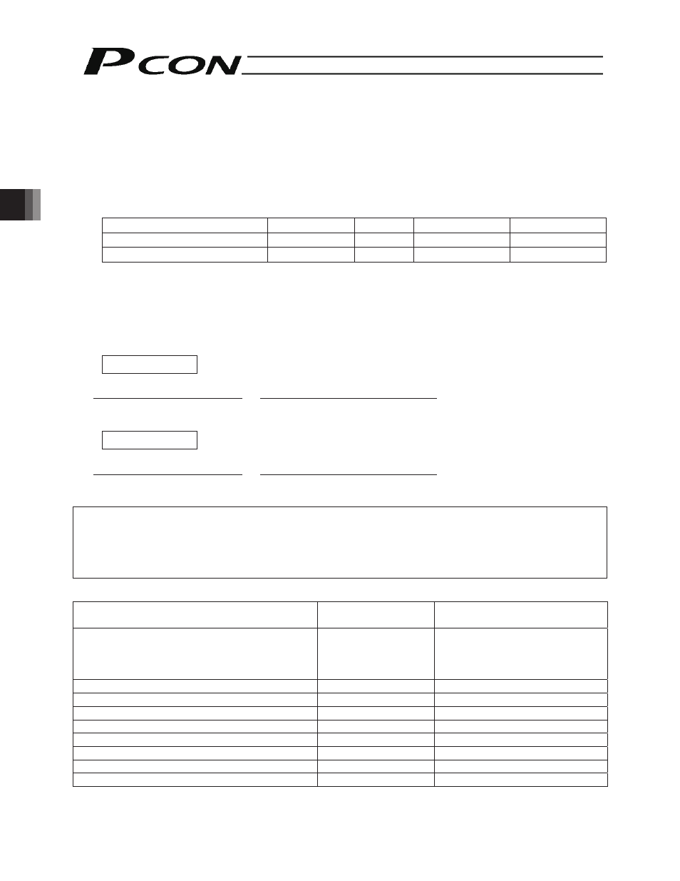
Setting Parameters Required for Operation
The following parameters must always be set prior to every operation.
(These parameters are all you need to set to perform operations that only involve positioning.)
(1) Electronic
gear
User Parameter Nos. 65 and 66 (Electronic gear numerator and denominator)
Name
Symbol
Unit
Input range
Default (reference)
Electronic gear numerator
CNUM
-
1 to 4096
200
Electronic gear denominator
CDEN
-
1 to 4096
15
These parameters are used to determine the unit travel distance of the actuator per one pulse in input command
pulse train.
Unit travel distance of linear-motion axis = Minimum travel unit (1, 0.1, 0.01 mm, etc.)/pulse
Unit travel distance of rotational axis = Minimum travel unit (1, 0.1, 0.01 deg, etc.)/pulse
Calculation Formula for Electronic Gear
Linear-motion axis
Electronic gear numerator (CNUM)
Encoder pulses (Pulse/rev)
Electronic gear denominator
(CDEN)
=
Ball screw lead length (mm/rev)
x Unit travel distance (mm/Pulse)
Rotational axis
Electronic gear numerator (CNUM)
Encoder pulses (Pulse/rev)
Electronic gear denominator
(CDEN)
=
360 (deg/rev) x Gear ratio of rotational axis
x Unit travel distance (deg/Pulse)
Reference
The actuator speed is calculated as follows:
Speed = Unit travel distance x Input pulse frequency (Hz)
Take note that if the unit travel distance is too small, the actuator may not be able to reach the maximum speed.
Table of encoder pulses and lead lengths for different models
Actuator type(s)
Encoder pulses
Pulse/rev
Lead length
SA5C/SA6C/SA7C/SS7C/SS8C
SA5R/SA6R/SA7R/SS7R/SS8R
RA2C/RA3C/RA4C/RA6C
RGS4C/RGS6C/RGD3C/RGD4C/RGD6C
800
Check the lead length shown on the
controller front panel
BA6/BA6U/BA7/BA7U
800
54
GRS
800 1
GRM
800 1.1
GR3LS/GR3LM
800 12
GR3SS
800 2.5
GR3SM
800 3
RTB (
Gear ratio
1/20)/ RTC (
Gear ratio
1/20)
800 18
RTB (
Gear ratio
1/30)/ RTC (
Gear ratio
1/30)
800 12