8 wiring the emergency stop circuit, 1 cutting off the drive signal (standard) – IAI America PCON-PO User Manual
Page 36
24
3. Installation and W
iring
3.8
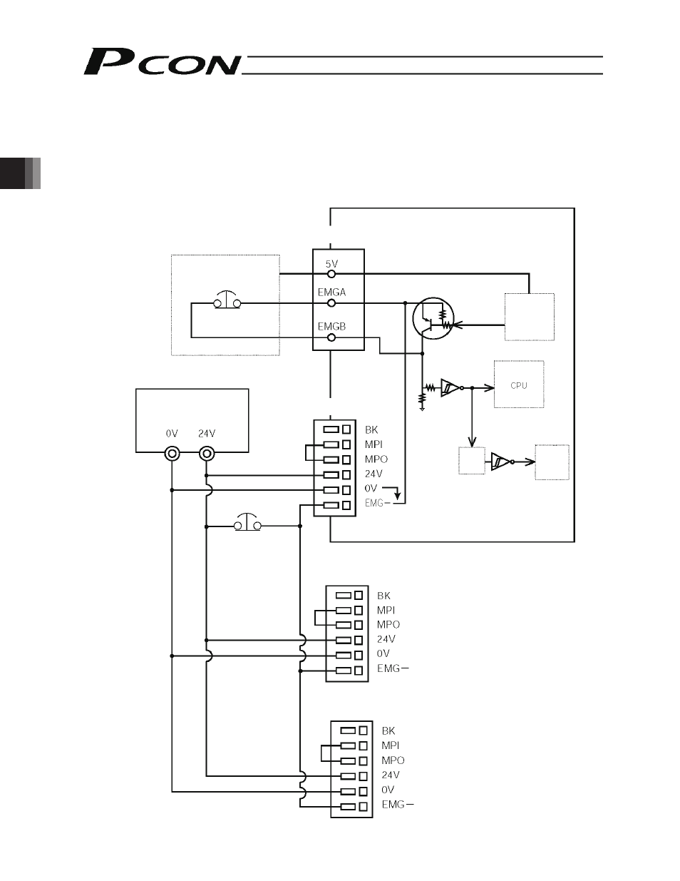
Wiring the Emergency Stop Circuit
3.8.1
Cutting Off the Drive Signal (Standard)
Connect one side of the external EMG switch to the positive side of the 24-VDC power supply, and connect the other
side to the BK terminal.
(Note) The EMG switch on the teaching pendant works only on the controller connected to the switch.
PCON-PL/PO controller
Power-supply
terminal block
Power-supply
terminal block (2nd)
SIO connector
Teaching pendant
EMG switch
24-VDC input power
supply
(Max. 2 A per unit)
External EMG switch
Connection
detection
signal (H)
SIO
connector
connection
detection
circuit
EMG signal
detection (H)
Time
constant
Drive stop
signal (L)
Motor
drive
circuit
Power-supply
terminal block (3rd)
This manual is related to the following products: