9 connecting the actuator, 1 motor relay cable – IAI America PCON-PO User Manual
Page 39
27
3. Installation and W
iring
3.9 Connecting
the
Actuator
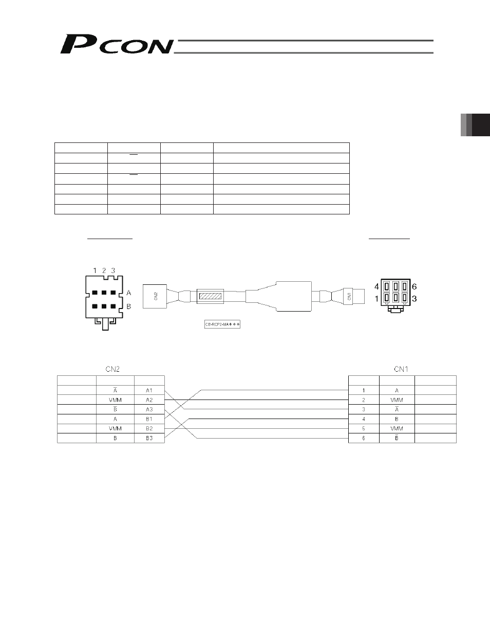
3.9.1
Motor Relay Cable
• Connect the motor relay cable to the MOT connector.
Signal table of controller-end connector (CN2)
Pin No.
Signal
Wire color
Description
A1
A
Orange
Motor drive line (phase -A)
A2
VMM
Gray
Motor power line
A3
B
White
Motor drive line (phase -B)
B1
A
Yellow
Motor drive line (phase +A)
B2
VMM
Pink
Motor power line
B3
B
Yellow (Green) Motor drive line (phase +B)
Controller end
Actuator end
CN2 pin layout
CN1 pin layout
Orange
Gray
White
Yellow
Pink
Yellow (Green)
Yellow
Gray
Orange
Yellow (Green)
Pink
White
Cable color
Signal
abbreviation
Pin No.
Cable color
Signal
abbreviation
Pin No.
Housing: SLP-06V
(J.S.T.
Mfg.)
Socket contact: BSF-21T-P1.4
Housing: 1-1318119-3
(AMP)
Receptacle contact: 1318107-1