S/hart, profibus pa, o, Setting with one inductive proximity switch, Setting with two inductive proximity switches – Burkert Type 8635 User Manual
Page 51
8635 - 49
I
NDUCTIVE PROXIMITY SWITCHES
(S/HART, PROFIBUS PA, O
PTION
)
Settings
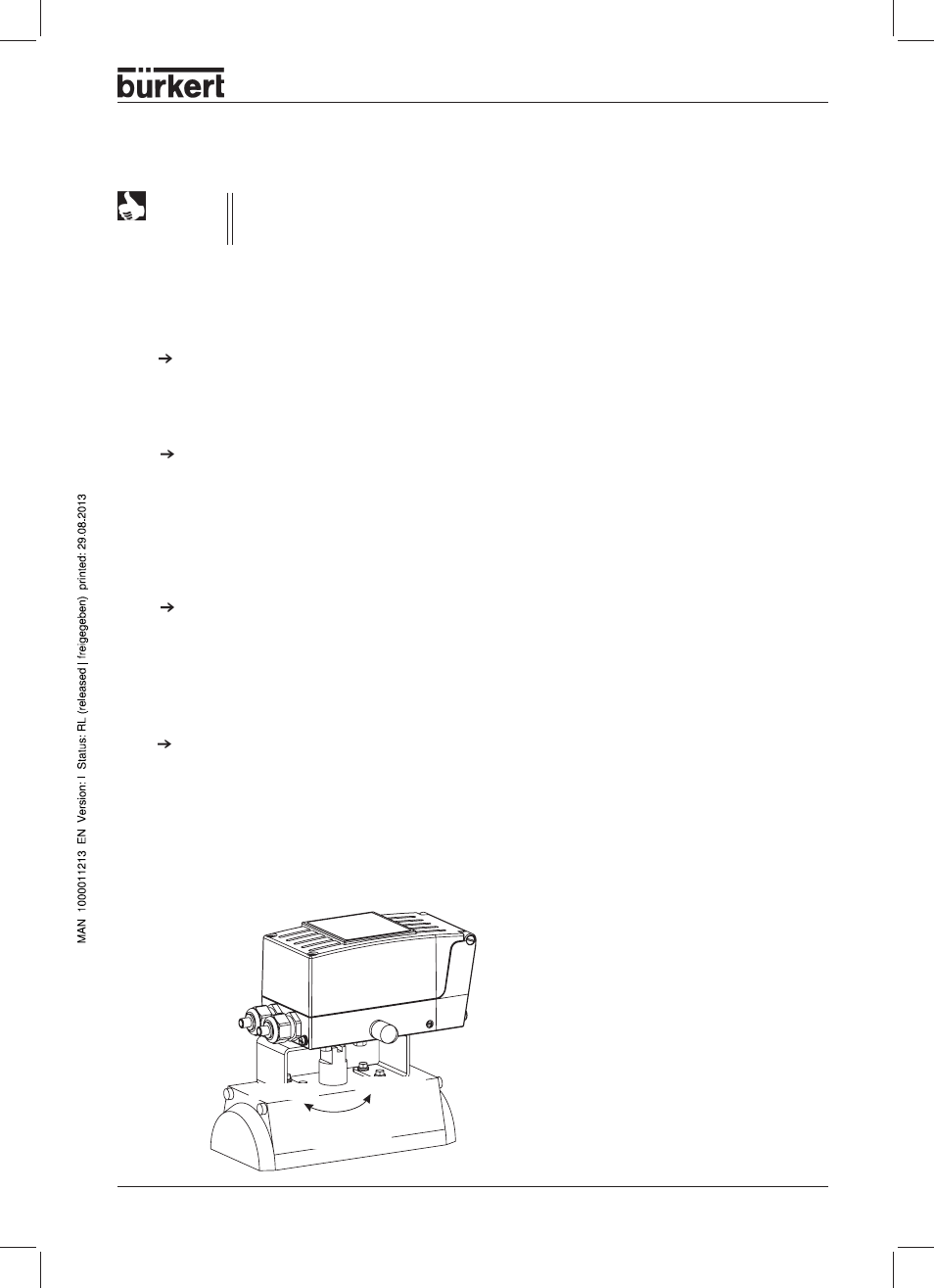
Definition of the end positions with part-turn actuators
Setting with one inductive proximity switch
The upper end position is to be set (Position 1 with part-turn actuators)
Move the actuator in the manual mode to the position in which initiation is to take place. Turn adjusting
wheel SR1 to the right until the current jumps from
≥ 2.1 mA to ≤ 1.2 mA.
The lower end position is to be set (Position 2 with part-turn actuators)
Move the actuator in the manual mode to the position in which initiation is to take place. Turn adjusting
wheel SR1 to the left until the current jumps from
≥ 2.1 mA to ≤ 1.2 mA.
Setting with two inductive proximity switches
The upper end position is to be set (Position 1 with part-turn actuators)
Move the actuator in the manual mode to the position in which initiation is to take place. Turn adjusting
wheel SR2 to the right until the current jumps from
≥ 2.1 mA to ≤ 1.2 mA.
On turning the adjusting wheel, take care that the other adjusting wheel is not turned.
The lower end position is to be set (Position 2 with part-turn actuators)
Move the actuator in the manual mode to the position in which initiation is to take place. Turn adjusting
wheel SR2 to the left until the current jumps from
≥ 2.1 mA to ≤ 1.2 mA.
On turning the adjusting wheel, take care that the other adjusting wheel is not turned.
First put the device into operation, as described in the chapter
Operation and Control
Functions. The function AUTOTUNE must have been executed, so that the actuator stroke
is displayed correctly.
NOTE
SIDE Control
Position 1
Position 2
Part-turn actuator