Electrical connection (profibus pa) – Burkert Type 8635 User Manual
Page 48
46 - 8635
I
NSTALLATION
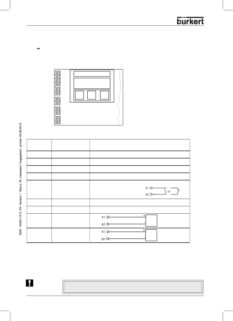
Terminal
designation
Allocation
External connection
BUS (+)
PROFIBUS-PA (IN)
to IEC 1158-2 (either polarity between input terminals)
BUS (-)
PROFIBUS-PA (IN)
BUS (+)
PROFIBUS-PA (OUT)
to IEC 1158-2 (either polarity between output terminals)
BUS (-)
PROFIBUS-PA (OUT)
81
Binary input
connected via switch (make contact)
to terminal 82
82
Binary input
N.C.
not connected
N.C.
not connected
41 +
Initiator 1 + (option)
42 -
Initiator 1 - (option)
51 +
Initiator 2 + (option)
52 -
Initiator 2 - (option)
Electrical connection (PROFIBUS PA)
ATTENTION!
During the electrical connection of the inherently safe circuits, always observe the
data in the attached Certificate of Conformity!
Use screened cable for connecting the bus and the binary input in order to assure reliability and EC
conformity. The cable screens can be attached using the clamping screw (on the post between the M20
bushings). The cable screens must be attached at both ends. On the outside of the housing there is a
further screw for further connection to a suitable earthing (grounding) point.
To make electrical connections, open the cover of the SIDE Control
(PROFIBUS PA) by
unscrewing the 2 screws.
Configuration of the terminals
51 (+)
Switching amplifier
to EN 50227
Switching amplifier
to EN 50227
81
N.C.
N.C.
41 (+)
42 (-)
52 (-)
Bus (+)
Bus (-)
Bus (+)
Bus (-)
82