Connector pin assignments, Console communications, Table b.1 – Avaya P130 User Manual
Page 152
Appendix B Specifications
138
Avaya P130 User’s Guide
Connector Pin Assignments
Console Communications
For direct Console communications, connect the Avaya P130 to the Console
Terminal using the supplied RJ-45 crossed cable and RJ-45 to DB-9 adapter.
For remote Console communications through a dial-up modem, connect the P130 to
a modem using the supplied RJ-45 cross cable and RJ-45 to DB-25 adapter.
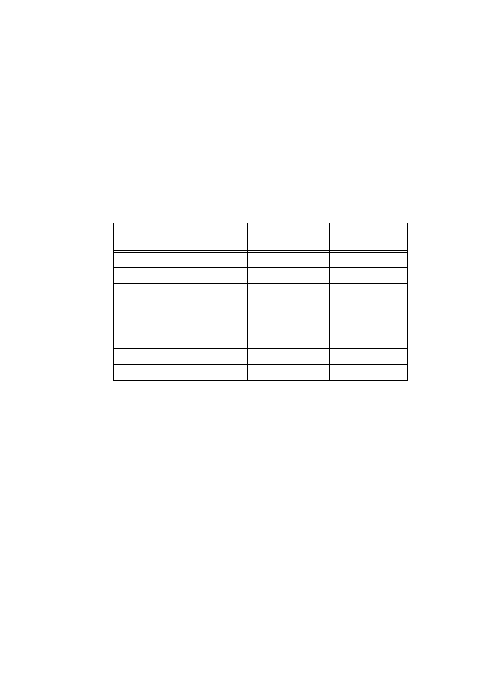
Table B.1
Pinout of the Required Connection for Console Communications
P130 RJ-45
Pin
Name
Terminal DB-9 Pins
Modem DB-25 Pin
1
For Future Use
NC
1
(see Footnote)
1 Pin 1 of the Modem DB-25 connector is internally connected to Pin 7 GND
2
TXD (P130 input)
3
3
3
RXD (P130 output)
2
2
4
CD
4
8
5
GND
5
7
6
DTR
1
20
7
RTS
8
4
8
CTS
7
5