Alpha Technologies XM3-HP Series - Technical Manual User Manual
Page 94
94
017-882-B0-001 Rev. C2 (10/2013)
4.0
Maintenance
4.3.2.2 On-Site Power Supply Preventive Maintenance, continued
4.3
Power Supply System Maintenance, continued
4.3.2 Periodic Maintenance Tasks, continued
4.0
Maintenance, continued
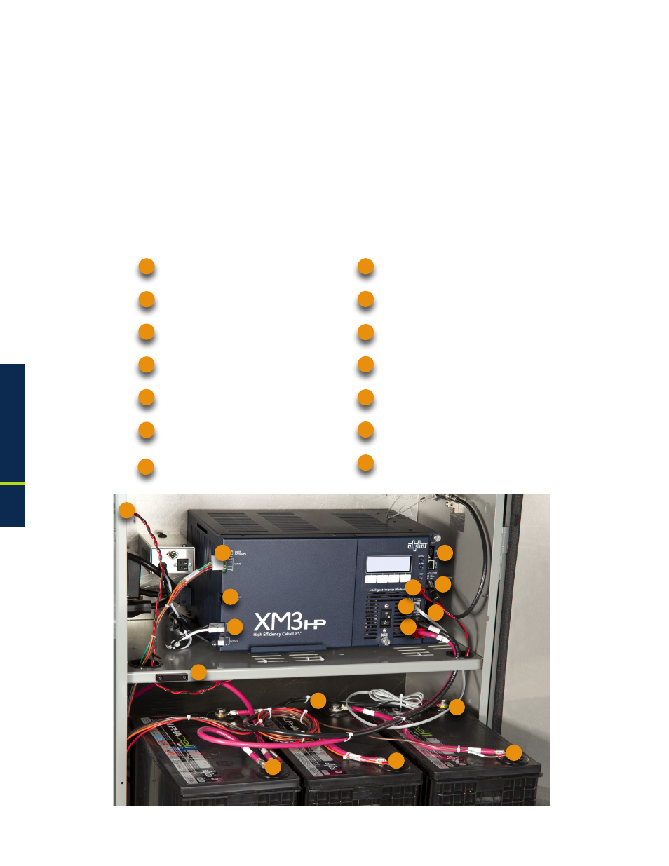
Smart AlphaGuard Harness
Battery Connector to Inverter
Negative Terminal to Center Battery
and PTS
Precision Temperature Sensor (PTS)
Positive Battery Terminals to Smart
AlphaGuard (3, Red)
Local Remote Indicator (LRI)
DSM3 Battery Sense Harness connection point
AlphaDOC Dual Output Connectors
LRI Connection to Power Supply
Negative Battery Terminal (1, Black)
8
9
10
4
1
3
2
5
6
Tamper Switch
RF Connector/DSM3
11
12
APPs Card
7
DSM3 Tamper Switch Connector
13
14
1
3
2
4
9
10
7
5
12
5
5
11
13
14
6
8
Fig. 4-1, XM3-HP System Components
3. Power Supply component inspection
a. Before physical inspection of the Power Supply, verify normal operation on the XM3
Smart Display. Clear all Active Alarms before proceeding.
b. Check physical condition of Power Supply; remove any dust or debris built up in or
around openings.
c. Inspect all cabling and connections of the Power Supply system (see Fig. 4-1). Verify that
all cabling is intact and all connectors are properly seated; resolve as needed.